6 accessories required but not supplied, 7 installation drawings – Northern Airborne Technology 211 User Manual
Page 14
Model 211 Voice Activated Switch
SM211 Installation and Operation Manual
Section 2 Rev: 1.00
Issue 2
Page 2-4
ENG-FORM: 805-0115.DOT
CONFIDENTIAL AND PROPRIETARY TO NORTHERN AIRBORNE TECHNOLOGY LTD.
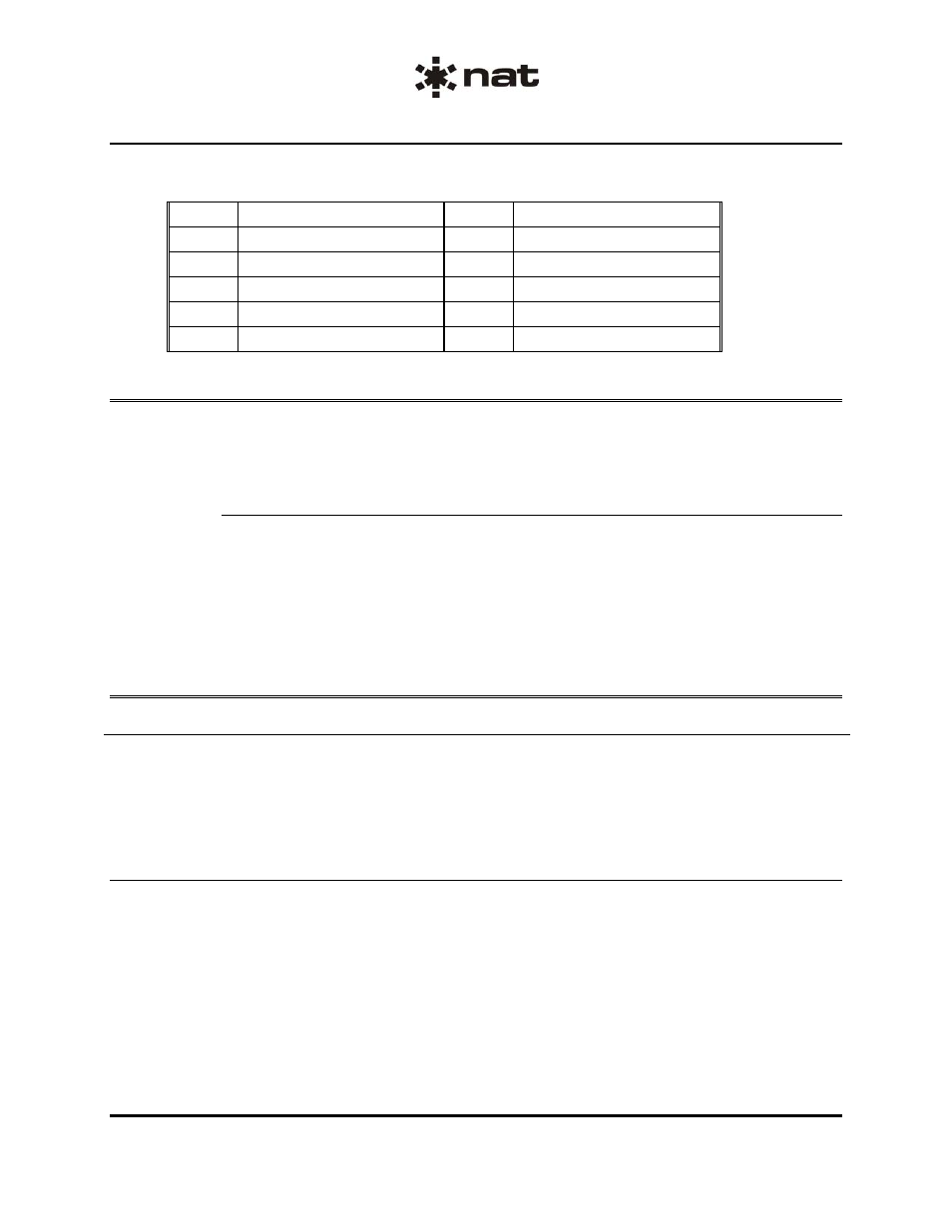
The table below shows the pin identifications for the 9-pin connector:
PIN DESCRIPTION
PIN DESCRIPTION
1
AUD IN LO
6
AUD IN HI
2
PWR GND
7
POWER IN (28 VDC)
3
AUD OUT LO
8
4
AUD OUT HI
9
CHASSIS GND
5 THLD
ADJ
2.6
Accessories Required But Not Supplied
To complete the installation, the 211 requires a crimp Installation kit, 211-IKC. The kit consists of the
following:
Installation kit 211-IKC (NAT Part #: D09SL-IKC)
Quantity
Description
NAT Part #
1
D-min 9 Socket Housing
20-21-009
9
MS Crimp Socket
20-26-901
1*
Jack Screw Set
20-27-002
1*
Lock Clip set
20-27-004
1
9 Pin Connector Hood
20-29-009
* Use as required. See below for assembly.
2.7
Installation Drawings
DOCUMENT REV.
DESCRIPTION
TYPE
SERIAL
NO.
211\211
1.20
Voice Activated Switch
Outline - Installation
All
Section 2 ends following the above documents