Olson Technology HLR3830 User Manual
Page 6
025-370539 REV X1
Page 6
INTERNAL ADJUSTMENTS AND TEST POINTS
The only internal user adjustment for the RPT-323x is the RF input PAD. This PAD is changed according to the number of
channels that will be loaded.
REVERSE INPUT RF LEVEL SETTING
The return RF level should be set using the reverse pad on the HLR3830 main board. The internal pad in the return transmitter is
for laser OMI matching, not for level setting. Monitor the –20db test point on the transmitter and adjust the reverse pad on the
HLR3830 main board for the correct level from the RF drive table (see page 7) for the transmitter type being used.
RECOMMENDED RF DRIVE LEVEL
Laser Transmitter Option
RF Input
RF Input –20db Test Point
RPT-3234-SA/30x (FP)
+31.0dBmV / Chan
+11.0dBmV / Chan
RPT-3235-SA/30x (DFB)
+31.0dBmV / Chan
+11.0dBmV / Chan
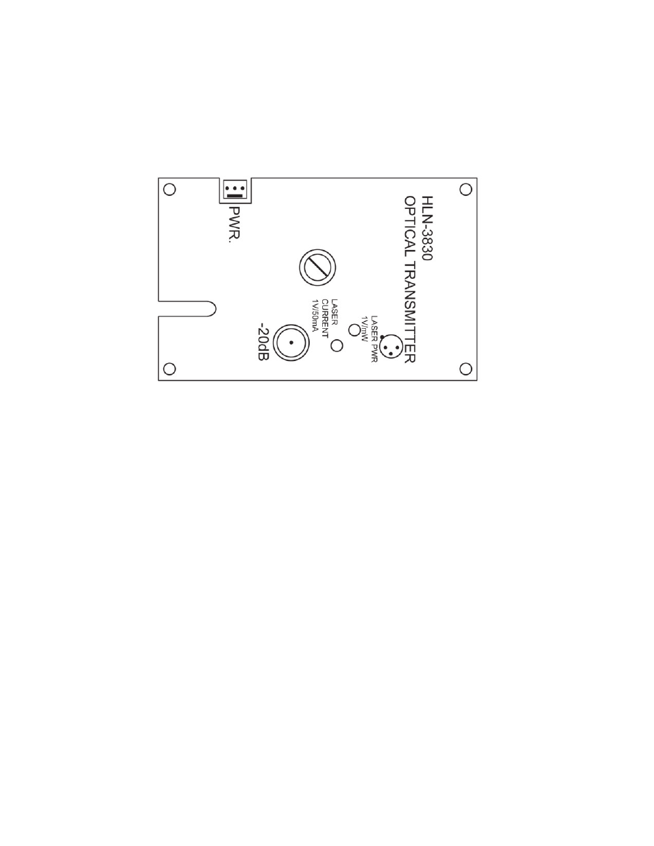
EXTERNAL ADJUSTMENTS AND TEST POINTS
There are no external adjustments. There are three test points that monitor optical output power, laser current, and a -20dB RF
input test point. The ‘LASER PWR’ test point is calibrated to match the output of the laser at a 1VDC per milliwatt scale. This
means if the laser has an optical output of 1.1mW, the test point will read 1.1VDC. The ‘LASER CURRENT’ test point is used to
measure the current that the laser is drawing. This test point does not work like that of the Harmonic transmitters. The ground
lead for the multimeter probe should grounded to a ground in the node for both the “LASER PWR’ and the ‘LASER CURRENT’
test points. The ‘LASER CURRENT’ test point is for historical records, as the laser ages the current will go up. The -20dB RF
input test point is to aid in setting up the transmitter for proper loading. This will be covered in a later section.