Olson Technology LCM-550x1 User Manual
Page 4
025-000329 REV C
Page 4
2.) CHANNEL SELECTION
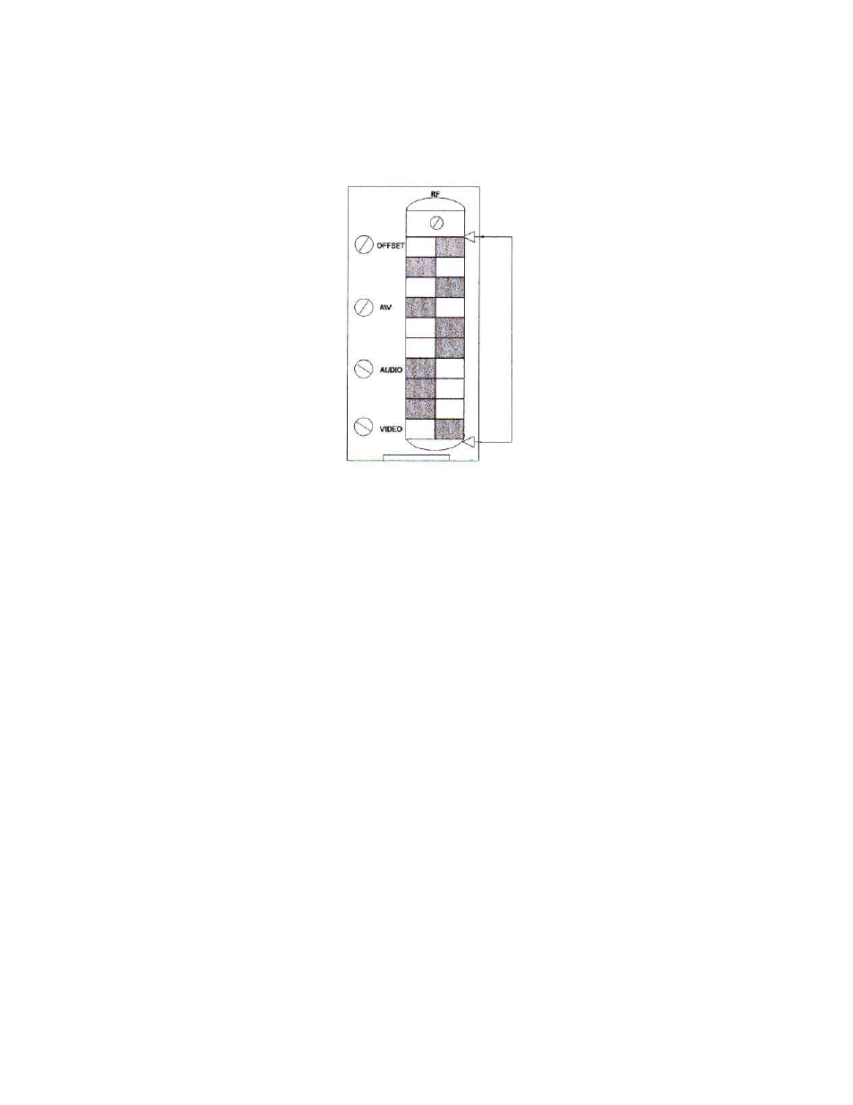
Channel frequencies are selected by setting the 10-position DIP switch (visible through the vertical
slot in the front panel). The front panel is illustrated in figure 1.
Channel Select
Figure 1 – LCM-550 Front Panel
Switch-setting codes for standard channels are shown in Figure 2 and on the code card provided with the
system. Switch-setting codes for HRC channel frequencies can be found in Table 2 and Figure 3 in this
manual. The front panel illustration in Figure 1 shows a switch properly set for standard channel 2.
3.) F.C.C. OFFSET ADJUSTMENT
F.C.C. Offset frequencies are shown in Table 1 and summarized on the code card provided with the
system. To adjust the frequency of a selected channel to provide the correct F.C.C. offset, look up its
offset frequency in Table 1 (or use the summary on the code card). Remove the video input and
connect a counter to the RF output of the LCM-550. Use the front panel offset adjust control to set
the output frequency to the correct value.