Olson Technology OTDV-1250 User Manual
Page 4
Model OTDV-1250, 025-000571 Rev. X5
4
www.olsontech.com
GENERAL FEATURES
The Olson OTDV-1250 Video/Stereo Audio, Data and Ethernet Fiber Optic Link provides a very high-quality system for
transporting baseband NTSC RS-250 or PAL B, D, G, H and I video signals, stereo audio signals and bidirectional data
with complete EMI immunity via multimode or single-mode optical fiber. The combination of video, stereo quality audio,
data for touch screens, pan, tilt & zoom or pure data transport for communications and the addition of auto-negotiating
10/100Mb/s Ethernet make these links ideal for broadcast, contribution and distribution quality V/A/A transport, tele-
conferencing, distance learning, and surveillance applications. Each unit is built in a rugged, shielded enclosure. Units
are available with four channels of audio and unidirectional transport options.
The defining feature of the OTDV-1250 is versatility. While there are numerous fiber optic broadcast transport links
available, the addition of user/field-swappable SFP modules allows the unit to be rapidly reconfigured for any conceiv-
able fiber requirement
All signals are handled using state-of-the-art digital techniques resulting in no degradation in performance regardless of
the fiber type and distance. All signals are digitized to a single serial data stream that easily fits into Gb/s data stream.
Extensive use of overhead messaging allows the two units to be aware of problems at the far end.
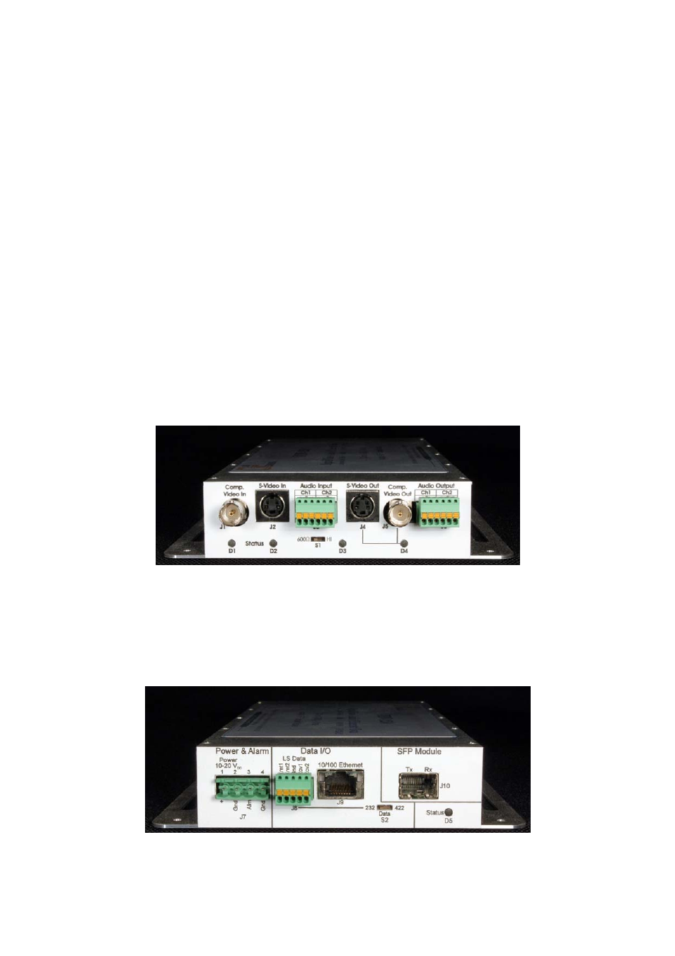
TRANSMIT SIDE
The left side is the transmit side. J1 is the composite video transmit. J2 is the S-video transmit. J3 is the stereo audio
transmit. The right side is the receive side. J4 is the composite video receive. J5 is the S-video receive. J6 is the stereo
audio receive. D1, D2, D3 & D4 give the status of the unit. Switch S1 selects whether the audio input is configured to be
high impedance or 600 Ohms.
POWER, DATA, ETHERNET, AND OPTICS SIDE
The left side is the power and alarm section. Pins 1 & 2 of J7 are the DC power input. Pins 3 and 4 are the alarm output.
The center section is the data interface. J8 is the low-speed data interface. Switch S2 is used to select RS-232 or RS-422.
J9 is the bidirectional 10/100Mb/s Ethernet data port. The right side contains the SFP module interface (J10) and the unit
status LED (D5).