Olson Technology OTM-3000 (PAL I) User Manual
Page 3
025-000137 REV B
Page 3
Figure 1
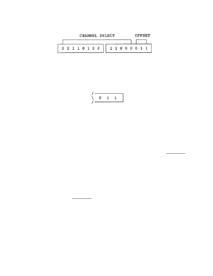
FRONT PANEL DIP SWITCHES
0 = Switch in DOWN Position
1 = Switch in UP Position
The last 3 DIP switches on the far right are used to select offset operation with certain versions of the
OTM-3000. On the OTM-3000 I, the switch should be left set as shown below.
4) VIDEO MODULATION ADJUSTMENT
A)
Connect a video source of approximately 1V p-p to the video input connector (75 ohms input Z) on
the rear panel. The video should be of a reasonably bright scene to ensure setting at peak modulation
levels.
B)
Rotate the video modulation level adjust control slowly clockwise until the video overmodulation
LED just turns on. The light may blink with differences in average picture level. CAUTION: If the
modulation is set too high, compression or lack of contrast will occur during high intensity scenes.
5) AUDIO MODULATION ADJUSTMENT
A)
Connect an audio source of 300mV p-p (minimum) to the balanced audio input connector (600 ohms
input Z) on the rear panel. The source should be typical of the program material to be carried.
B)
Rotate the audio modulation level adjust control slowly clockwise until the audio overmodulation LED
just begins to blink. CAUTION: Overmodulation can result in severe distortion in some TV sets. Set
this control at peak program levels.
6) RF AND AURAL CARRIER LEVEL ADJUSTMENT
A)
Using a field strength meter or spectrum analyzer, set the video carrier to the desired level with the RF
output level adjust control.
B)
Tune the field strength meter to the aural carrier (6.0 MHz above the video carrier).