ONICON System-30 LonWorks BTU User Manual
Page 26
11451 Belcher Road South, Largo, FL 33773 • USA • Tel +1 (727) 447-6140 • Fax (727) 442-5699 • [email protected]
System-30 BTU Measurement System LON 05/14 - 0668-2 / 18337
Page 26
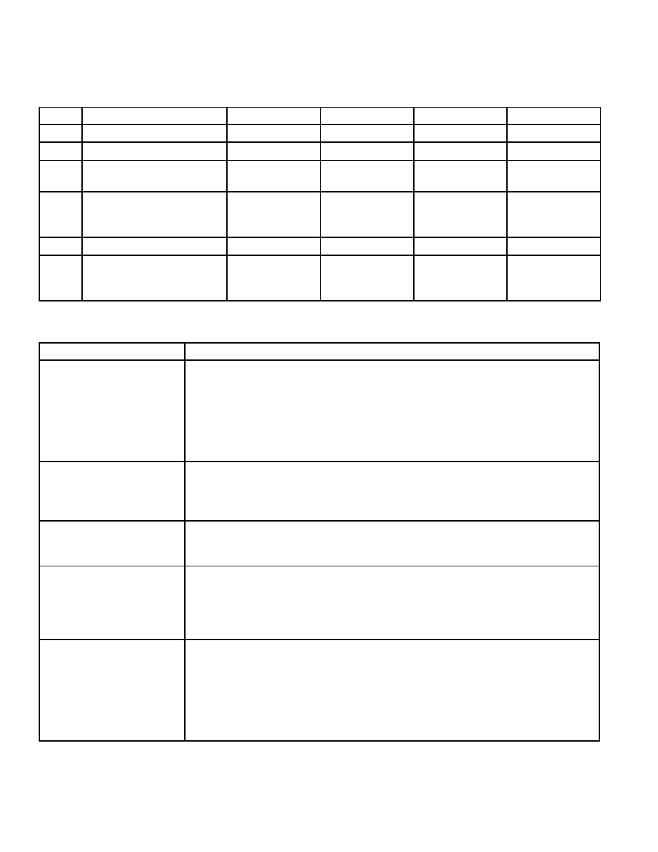
4.8.1 Commissioning Worksheet
Please read all installation instructions carefully prior to proceeding with these steps.
Wiring diagrams are located in the appendix. Use the following worksheet for checking
off the commissioning steps and recording measured values:
STEP TEST / MEASUREMENT S/N:
S/N:
S/N:
S/N:
1.
Meter location
2.
Supply voltage verified
3.
Verify diagnostic LED’s
are flashing
4.
Note and record
temperature readings for
T1, T2 & delta T
5.
Note and record flow rate
6.
Confirm contact closure
output operation for
Mode 1 & Mode 2
TROUBLESHOOTING GUIDE FOR ONICON SYSTEM-30 BTU MEASUREMENT SYSTEMS
NOTE: Also refer to the COMMISSIONING GUIDE located on the preceding pages.
REPORTED PROBLEM:
POSSIBLE SOLUTIONS:
No Flow Signal/ Energy
Signal
(While hydronic system
is active)
•
Verify 24 VAC / VDC supply voltage to the System-30.
•
Verify correct wiring to the System-30 (see wiring diagram).
•
Check turbine for clogging due to debris.
•
If none of the above, double check hydronic system to
ensure that flow is really present in the line.
•
NOTE: Flow meter function cannot be verified by blowing on the turbine.
The sensing system requires a conductive liquid to operate.
Displayed Flow Rate too
high or too low
•
Verify that System-30 isolation valves are fully open and
bypass valve is fully closed (if bypass is used).
•
Check turbine(s) for debris.
•
Verify supply voltages.
Displayed Temperature
too high or too low vs.
expected values.
•
Verify that thermowell is inserted into the flow stream and
that the temperature sensor is completely inserted into the
thermowells.
Device is not
communicating with the
Lon Talk network.
• What is the state of the service pin LED?
• Is it flashing? A flashing service pin LED indicates that the Lon module
has not been commissioned. (See Appendix A-6)
• Is it off? A service pin LED that is off indicates that the Lon module is
commissioned and operating normally.
Communications with
the Lon Talk network is
intermittent.
• Is the network properly terminated? The Lon TP/FT bus can be
terminated in 2 different ways.
• A single RC filter can installed at any point on a free topology network.
A dual termination scheme is used with 2 RC filters installed at the
ends of bus networks. (Refer to the Appendix A-7 for details.)
• What type of cable is used to wire the network? TP/FT networks
should only use twisted shielded pair cable. (Belden 85102 or equiv.)
For technical assistance, contact ONICON Incorporated at (727) 447-6140.