OpenEye CM-512 Quick Start User Manual
Cm-512 | high speed dome camera quick guide
This quick operation guide is a quick reference for users to install and operate the dome
camera and only provides basic information on the camera’s settings and operation. Before
attempting to connect, configure and operate the dome camera, please read the installation
guide and the user manual thoroughly.
Box Contents
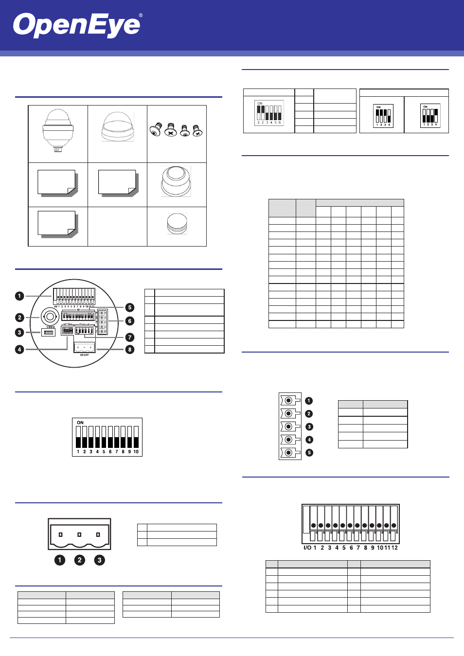
Dome Switch Definition
1
Alarm Inputs
2
BNC Output
3
Console Connector
(Reserved)
4
Communication Switch
5
Camera ID Setting
6
RS-485 Connector
7
Protocol Settings
8
Power Connector
Communication Switch Setting
The table below shows the function of each switch within the Communication Switch on the
dome back plate.
Dome Control Protocol Setting
Refer to the table below and select a protocol and baud rate appropriate for your installation,
based on the control device. Adjust the Protocol Switch on the dome camera back plate. For
example, the protocol switch should be set as shown if you are using the Pelco D protocol,
with the switch number of 01 and a baud rate of 2400. For more switch configurtion details,
refer to the user manual
RS-485 Connector
The dome camera uses the RS-485 interface to communicate with a connected control device.
Connect a control keyboard to the speed dome using the terminal block. OpenEye recom-
mends using CAT 5 cables for RS-485 communication with a maximum length of 4000 feet
(1219 meters) for 24-gauge wire. If the total cable length exceeds 4000 feet, use a repeater to
maintain the signals. Refer to the table below for pin definition and wiring.
Pin
Definition
1
R-
2
GND
3
R+
4
T-
5
T+
Power Connector
Refer to the this diagram for power connector definition before wiring.
Apply Alarm I/O
The CM-512 supports 4 digital alarm inputs and 2 digital alarm outputs. Please make sure
the alarm connections are properly wired before starting to configure alarm-related settings.
Please refer to this pin definition table for alarm system wiring.
Power Wire Length Specifications
CM-512 | High Speed Dome Camera Quick Guide
www.openeye.net
Wire Gauge
Maximum Distance
22
27 feet
20
44 feet
18
69 feet
16
110 feet
Wire Gauge
Maximum Distance
14
175 feet
12
279 feet
10
444 feet
RS-485 Setting
Half-duplex
Full-duplex
Communication Switch
SW 1
RS-485 Setting
SW 2
SW 3
Termination
SW 4
Line Lock
SW 5
System Initialization
SW 6
Reserved
1
AC IN +
2
Frame GND
3
AC IN -
Pin
Definition
Pin
Definition
1
Alarm Out NO1
7
Alarm Out COM 2
2
Alarm Out NC 1
8
GND
3
Alarm Out COM 1
9
Alarm In 4
4
GND
10
Alarm In 3
5
Alarm Out NO 2
11
Alarm In 2
6
Alarm Out NC 2
12
Alarm In 2
Camera ID Setting
Change the camera ID if there is more than one camera on the same installation. The camera
ID is set using the camera ID switch on the back plate of the camera. For switch configuration
details, please refer to the user manual.
Note: No two cameras should have the same
camera ID, or a communication conflict
may occur.
Optical Cover
CM-816 Camera
Screws
Quick Start Guide
User Manual
Waterproof Gasket
Installation Manual
Lubricant
Protocol
Baud
Rate
Setting
Switch Setting
1
2
3
4
5
6
VCL
9600
OFF
OFF
OFF
OFF
OFF
OFF
Pelco-D
2400
ON
OFF
OFF
OFF
OFF
OFF
Pelco-P
4800
OFF
ON
OFF
OFF
OFF
OFF
Chiper
9600
OFF
OFF
ON
OFF
OFF
OFF
Philips
9600
ON
OFF
ON
OFF
OFF
OFF
OPTIX-3
9600
ON
ON
ON
OFF
OFF
OFF
AD422
4800
OFF
OFF
OFF
ON
OFF
OFF
DP-P
9600
ON
OFF
OFF
ON
OFF
OFF
Pelco-D
4800
ON
ON
OFF
ON
OFF
OFF
Pelco-D
9600
OFF
OFF
ON
ON
OFF
OFF
Pelco-P
2400
ON
OFF
ON
ON
OFF
OFF
Pelco-P
9600
OFF
ON
ON
ON
OFF
OFF
JVC
9600
ON
ON
ON
ON
OFF
OFF
Kalatel-485 9600
ON
OFF
ON
OFF
ON
OFF
Kalatel-422 4800
OFF
ON
ON
OFF
ON
OFF