OpenEye 200-Series Installation Manual User Manual
Tamper resistant indoor dome camera, Regulatory compliance hardware kit contents, Precautions
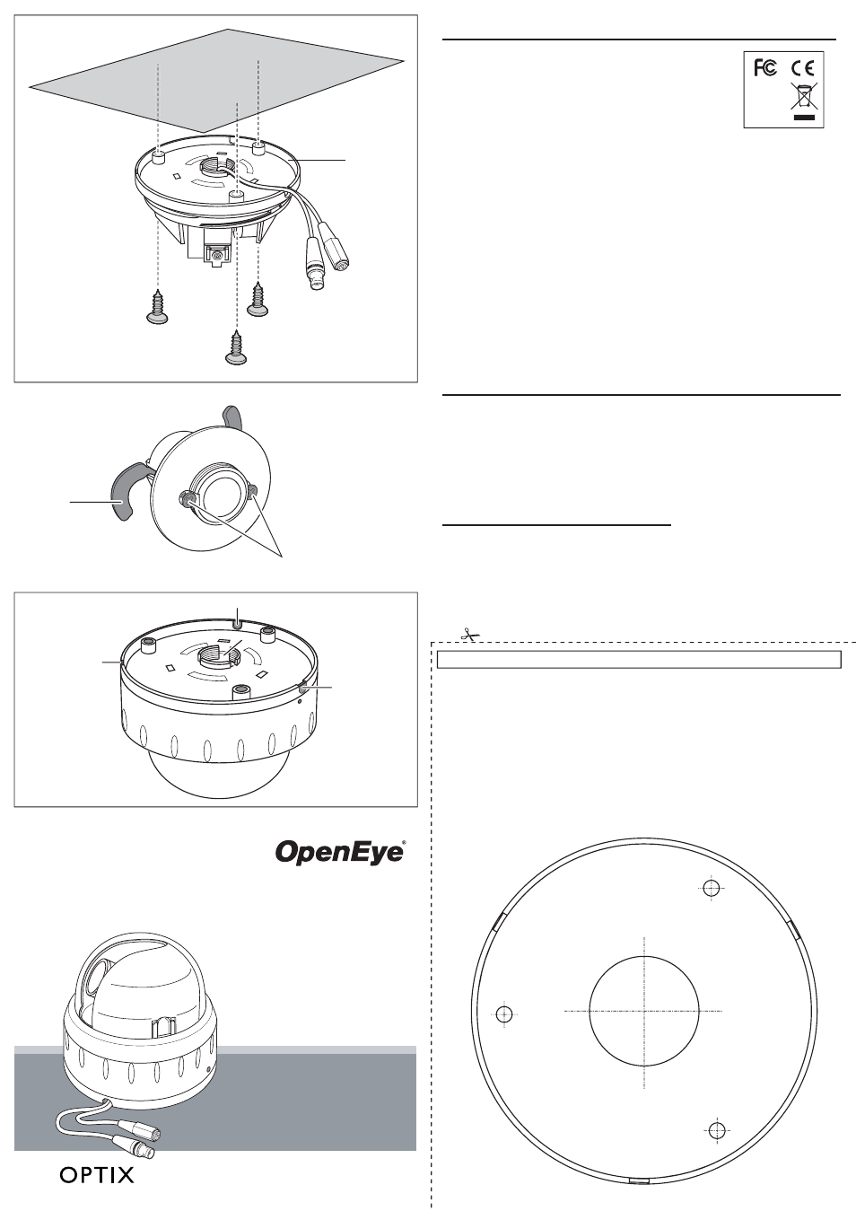
Surface Mount (In a wall or ceiling)
Template
Cable Access
A
B
Dome base
Locking arms
B1
B1
C1: Threaded base
C2: Screw access holes
C3: Side knock-outs
C1
C2
C2
C2
C3
C3
C3
C
Camera Installation
Please carefully read these instructions before using this product.
Save this manual for future use.
27789AG
Tamper Resistant Indoor
Dome Camera
CM-201
CM-205
CM-205-L9
CM-215
model no.
Loosen screws, but not remove
them,to first extend the locking arms.
Then tighten the screws sufficiently to
compress the arms to adjust to the
mounting surface; however, DO NOT
OVERTIGHTEN.
Using Quick Install Adaptor:
Cut a 1.3” (35 mm)
diameter hole in the mounting surface as indicated
by “T5”.
Using Screws: Use a ¼” (7.5 mm) drill bit and drill
three holes at the template positions “D5” and insert
a wall anchor in each hole. Use three D5 screws.
T5
D5
D5
D5
The cables are threaded through the base knockout
(shown in fig C1). The base is threaded for use with the
quick install adapter.
When mounting the dome on a surface with the three
D5 screws, use one of the side knock-outs as
indicated by C3 shown in fig C for cable entry.
See “Installing the dome enclosure” for instructions on
how to drill a hole on the side knock-out.
Regulatory Compliance
Hardware Kit Contents
RoHS
FCC COMPLIANCE:
This equipment has been tested and found to comply with the limits for a Class B digital device, pursuant to Part 15 of the
FCC Rules. These limits are designed to provide reasonable protection against harmful interference in as residential
installation. This equipment generates uses and can radiate radio frequency energy and, if not installed and used in
accordance with the instructions, may cause harmful interference to radio communications. However, there is no
guarantee that interference will not occur in a particular installation.
If this equipment does harmful interference to radio or television reception, which can be determined by turning the
equipment off and on, the user is encouraged to try \to correct the interference by one or more of the following measures:
• Reorient or relocate the receiving antenna.
• Increase the separation between the equipment and receiver.
• Connect the equipment into an outlet on a circuit different from that to which the receiver is connected.
• Consult the dealer or an experienced Radio/TV technician for help.
CISPR 22 WARNING:
This is a Class B product. In a domestic environment this product may cause radio interference in which case the user
may be required to take adequate measures.
POWER SUPPLY REQUIREMENTS:
For use with listed Audio/Video product and only connected to 15W or less power supply.
*Power supply should be a NEC Class 2 / LPS Supply.
EQUIPMENT MODIFICATION CAUTION:
Equipment changes or modifications not expressly approved by the manufacturer, the party responsible for FCC
compliance, could void the user’s authority to operate the equipment and could create a hazardous condition.
This class B digital apparatus complies with Canadian ICES-003.
Cet appareil numérique de la classe B est conforme à la norme NMB-003 du Canada.
FCC part 15 Class B
CE: EN55011
ICES-003
EN55022
CISPR 11
CISPR22
ANSI C63.4
CE: EN50130-4
CSA C22.2
Emissions
Immunity
Safety
Precautions
• Do not attempt to disassemble the camera module mounting within the dome. There are no user
serviceable parts within the camera module. Refer servicing to qualified service personnel.
• Handle the camera with care. Avoid dropping or shaking it. Improper handling or storage could
damage the camera.
• Regardless of whether the camera is in use or not, never face it toward the sun. Use caution when
operating the camera in the vicinity of spotlights or other bright lights and light reflecting objects.
• Do not operate the camera beyond its temperature, humidity, or power source ratings. Please refer to
the environmental information provided on the Camera Setup sheet
• 1/2”
Rubber
Grommet
• 3/4”
Rubber
Grommet
• Screw
Pack
• Torx
Driver
• Quick Install Adaptor
• Wire-Ended Power Adaptor Lead