OpenEye CM-150 User Manual
Lens specifications regulatory compliance, General specifications, Camera adjustments
Hardware Kit Contents
• 1/2” Rubber Grommet
• 3/4” Rubber Grommet
• Screw Pack
• Torx Driver
• Quick Install Adaptor
• Wire-Ended Power Adaptor Lead
Template
Cable access:
Surface Mount (Wall or Ceiling)
Using the Quick Install Adaptor:
Using screws:
T1
T2
Side Knock-out
Side Knock-out
Side Knock-out
Side Knock-out
Cable Access
T1
T1
T1
Create a 1.5” (38mm) hole in the mounting surface as
indicated by T2. The hole can also be used for cable access.
Drill four holes at template positions T1 and use the screws
and anchors provided with the camera if they are appropriate
for the mounting surface.
When mounting the camera on a surface with the provided
screws, use one of the side knock-outs, as indicated on the
template, for cable entry.
To thread the cables through the mounting surface, cut a 3/4”
(19mm) hole as indicated by the Cable Access markings
inside T2.
Lens Specifications
Regulatory Compliance
Emissions
Immunity
FCC part 15 Class B
CE: EN55011
ICES-003
EN55022
CISPR 11
CISPR22
ANSI C63.4
CE: EN50130-4
RoHS
FCC COMPLIANCE:
This equipment has been tested and found to comply with the limits
for a Class B digital device, pursuant to Part 15 of the FCC Rules.
These limits are designed to provide reasonable protection against
harmful interference in as residential installation. This equipment
generates uses and can radiate radio frequency energy and, if not
installed and used in accordance with the instructions, may cause
harmful interference to radio communications. However, there is no
guarantee that interference will not occur in a particular installation.
If this equipment does harmful interference to radio or television
reception, which can be determined by turning the equipment off and
on, the user is encouraged to try \to correct the interference by one or
more of the following measures:
Reorient or relocate the receiving antenna.
Increase the separation between the equipment and receiver.
Connect the equipment into an outlet on a circuit different from that to
which the receiver is connected.
Consult the dealer or an experienced Radio/TV technician for help.
CISPR 22 WARNING:
This is a Class B product. In a domestic environment this product
may cause radio interference in which case the user may be required
to take adequate measures.
POWER SUPPLY REQUIREMENTS:
For use with listed Audio/Video product and only connected to 15W
or less power supply.
*Power supply should be a NEC Class 2 / LPS Supply.
EQUIPMENT MODIFICATION CAUTION:
Equipment changes or modifications not expressly approved by
seller, the party responsible for FCC compliance, could void the
user’s authority to operate the equipment and could create a
hazardous condition.
This class B digital apparatus complies with Canadian ICES-003.
Cet appareil numérique de la classe B est conforme à la norme
NMB-003 du Canada.
General Specifications
Type / Format
Model No.
Lens Focal Length
Scanning Element
Image Picture Element
Effective Picture Element
Resolution (TV lines)
Minimum Illumination
S/N Ratio
Back Light Compensation
Exposure Control
Sync System
Gamma Compensation
Video Output
White Balance
Auto White Balance Range
Power Range
Power Consumption
Operating Temperature
Storage Temperature
CM-159
CM-150
9mm~22mm
4mm~9mm
NTSC
1/3” Sony SuperHAD CCD (Interline)
Imaging DSP
Sony SS-11X
500
1.2 Lux @ F1.6 (50 IRE)
48dB
Central Area for DC IRIS Lens
INT
0.45
Automatic White Balance
2500K – 9700K
DC 12V ±10%
1.8W (Max)
-10°C ~ +50°C
-20°C ~ +60°C
DC Type Auto IRIS Control
1.0Vpp, 75Ω Unbalanced
768(H) x 494(V)
2:1 Interlace
H15.734KHz / V :59.9Hz
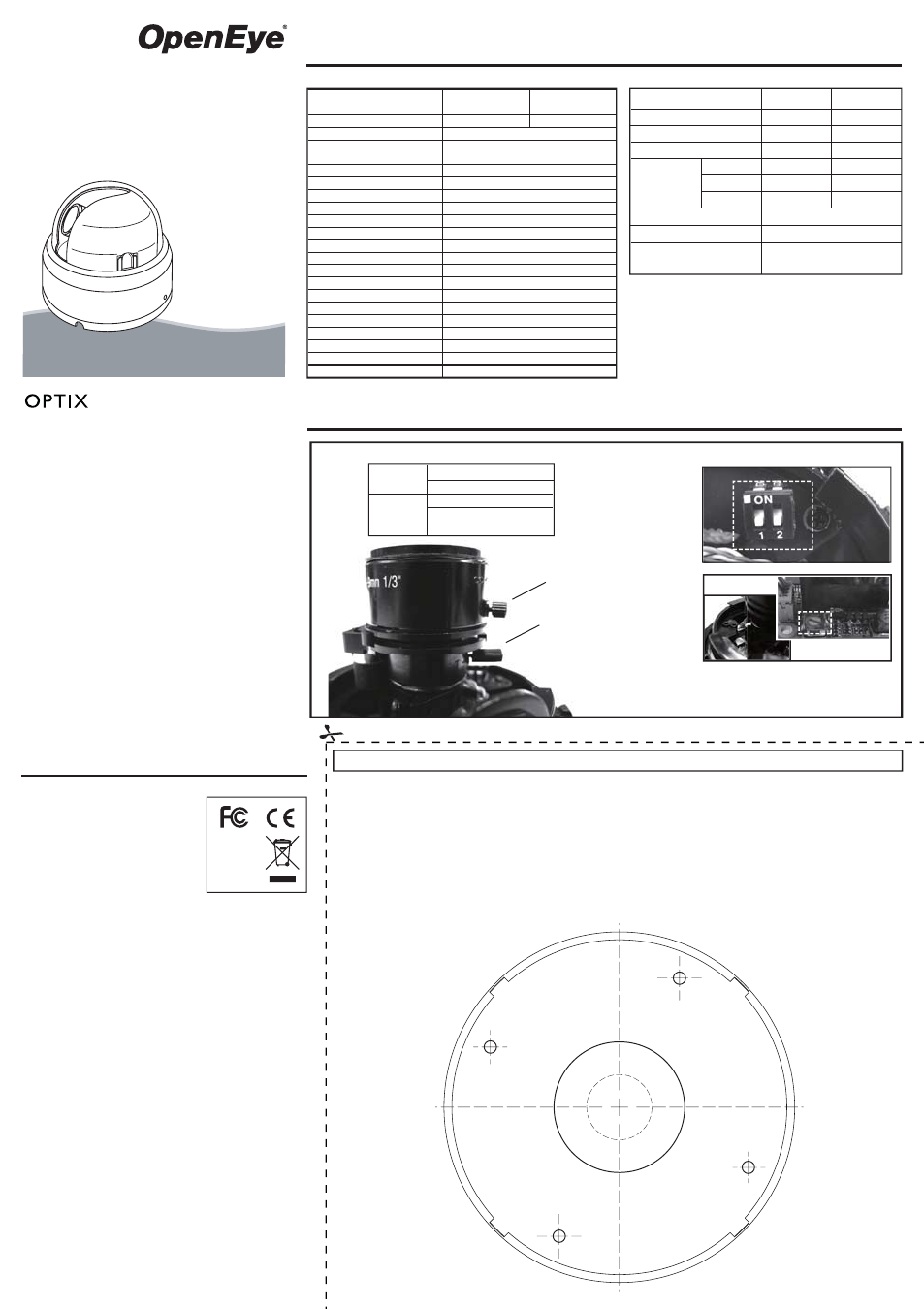
Camera Adjustments
A3
A4
* AI Level Adjustment is factory set;
it should not require adjustment.
A1
A2
Quick Installation Manual
CM-150
CM-159
model no
Tamper Resistant
Indoor Mini Dome
Please carefully read these instructions before using this product.
Save this manual for future use.
28395AC
A
Vari-Focal Lens
Switch 2
ON
OFF
Back Light Compensation
Auto Gain Control
OFF
(Normal Mode)
ON
(Turbo Mode)
Switch 1
Function Control Dip Switches
Focus Adjuster
A1 :
Field of View
Adjustment
A2 :
A3 : Function Control
Dip Switches
A4 : AI Level
Adjustment*
BLC
AGC-UP
Focal Length
F-No.
Iris Range
Minimum Object Distance
Field Of View
Diagonal
Horizontal
Vertical
4mm~9mm
F1.6
F1.6~F2.4
50cm
92.8º~39.4º
71.0º~31.6º
51.6º~23.6º
9mm~22mm
F1.8
F1.8~F360
15cm(6”)
39.0º~17.6º
30.7º~14.1º
22.7º~10.6º
ON/OFF
ON/OFF
AUTO
Low Light Chroma
Suppression