OpenEye CM-305 User Manual
Regulatory compliance, Tamper resistant outdoor dome camera, Rohs
T1
T2
Template
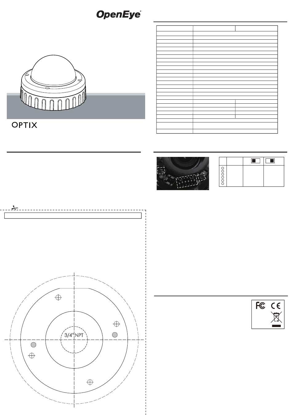
Cable Access Using Base Cable Entry
When the cables are threaded through the mounting
surface, create a 3/4” (19 mm) hole as indicated
“T4”.
Note: When mounting the dome on a surface with
the four T1 screws, use one of the side knock-outs
as indicated for cable entry
(see installation guide overleaf ).
Note: When mounting on a US Single Gang Box,
use the pre-drilled securing holes in the dome base
as indicated “T5”.
Do Not Open the holes at position “T5”.
Surface Mount (on a wall or ceiling)
Using Quick Install Adaptor:
Create an aperture in the mounting surface to a
diameter of 1.5” (38 mm) as indicated by “T2”.
Using Locking Arms:
Create an aperture in the mounting surface to a
diameter of 4.3” (110 mm) as indicated by “T3”.
Using Screws:
Create four holes at template positions ‘T1’, use the
screws and plugs provided in the screw kit where the
mounting surface is appropriate.
Cable Access
T1
T1
T1
T5
T3
T5
US Single Gang Box
US Single Gang Box
T4
• 1/2” Rubber Grommet
• 3/4” Rubber Grommet
• Screw Pack
• Torx Driver
• Wire-ended Power Adaptor lead
• Quick Install Adaptor (Optional)
Camera Installation
Please carefully read these instructions before using this product.
Save this manual for future use.
29713AB
Tamper Resistant Outdoor
Dome Camera
CM-305
CM-305-H
model no.
FCC part 15 Class B
CE: EN55011
ICES-003
EN55022
CISPR 11
CISPR 22
ANSI C63.4
CE: EN50130-4
Emissions
Immunity
Model No.
General Specifications
Camera Adjustments
Hardware Kit Contents
Image Sensor
Imaging DSP
IP Rating
Type / Format
Wide Dynamic Range
Minimum Illumination
Day / Night
Horizontal TVL
Service Monitor Jack
S/N Ratio
Focal Length
Iris Control
Synchronization
Video Output
White Balance
Auto White Balance Range
Backlight Compensation
Auto Gain Control
Operating Temperature
Heater
Power Consumption
Rated Amperature
Input Voltage
Weight
Dimensions
Housing / Dome Cover
1/3” Sony SuperHAD
Sony HQ-1
IP66
NTSC
No
0.6 lux @ F1.2 (50 IRE)
Yes
Day: 540 TVL / Night: 570 TVL
Yes, 2.5 mm (3/32) T/S Jack
>50dB
3.3 ~ 12 mm
DC Drive
INT / LL
1.0Vpp, 75Ω BNC Unbalanced
AWB, AWB-EX
2500 K ~ 11000 K (AWB-EX 2000 K ~ 18000 K)
Central Area
AGC-EX, AGC Normal
1.98 lbs (0.9 kg)
Dome : ø3.9" (100 mm) x H: 1.7" (45 mm)
Housing: ø5.3" (135 mm) x H: 1.9" (50 mm)
Gray / Clear
CM-305
CM-305-H
Regulatory Compliance
RoHS
FCC COMPLIANCE:
This equipment has been tested and found to comply with the limits for a Class B digital device, pursuant to Part
15 of the FCC Rules. These limits are designed to provide reasonable protection against harmful interference in a
residential installation.
This equipment generates, uses, and can radiate radio frequency energy and, if not installed and used in
accordance with the instructions, may cause harmful interference to radio communications. However, there is no
guarantee that interference will no occur in a particular installation.
If this equipment does cause harmful interference to radio or television reception, which can be determined by
turning the equipment off and on, the user is encouraged to try to correct the interference by one or more of the
following measures:
• Reorient or relocated the receiving antenna.
• Increase the separation between the equipment and receiver.
• Connect the equipment into an outlet on a circuit different from that to which the receiver is connected.
• Consult the dealer or an experienced Radio/TV technician for help.
CISPR 22 WARNING:
This is a Class B product. In a domestic environment this product may cause radio interference which case the
user may be required to take adequate measures.
POWER SUPPLY REQUIREMENTS:
For use with listed Audio/Video product and only connected to 15W or less power supply.
*Power supply should be a NEC Class 2 / LPS Supply.
EQUIPMENT MODIFICATION CAUTION:
Equipment changes or modifications not expressly approved by the manufacturer, the party responsible for FCC
compliance, could void the user’s authority to operate the equipment and could create a hazardous condition.
This class B digital apparatus complies with Canadian ICES-003.
Cet appareil numérique de la classe B est conforme à la norme NMB-003 du Canada.
DIP Switches
V-Phase
ALC
L.L.
D/N
AWB
FL
BLC
AGC
INT
OFF
NORMAL
OFF
OFF
EX
LL
ON
EX
ON
ON
NORMAL
OFF
N
O
N
O
I
T
C
N
U
F
1
2
3
4
5
6
The bank of DIP switches allows the
following settings to be made:
Line Lock (INT/LL)
In LL Mode, the V-Phase may be adjusted to compensate for connected supply phase differences. Only applicable
for 24vAC supply. When using a 12vDC power supply, the camera should be operated with INT (internal) sync.
DAY/NIGHT Mode (D/N)
When this switch is set to ON the camera will produce color images under normal lighting conditions. In reduced
light the camera will switch to Monochrome mode.
Auto White Balance (AWB Normal/AWB-EX)
AWB:
The camera operates in the normal AWB range (2700 K ~ 11000 K).
AWB-EX:
The camera operates in the extended AWB range (2000 K ~ 18000 K).
Flickerless Mode (FL/ON)
The camera reduces flicker in the image under fluorescent lighting.
Back Light Compensation (BLC)
When set to ON, this option improves the camera’s response to strong, unwanted lighting effects behind the
desired subject.
Low Light Sensitivity (AGC-EX/AGC Norm)
When set to EX, sensitivity in low light will automatically increased.
Selecting NORMAL will remove noise from the image, but will also limit the camera’s sensitivity.
Vertical Phase Adjustment (V-Phase)
Use this adjustment when using an 24vAC supply to align the camera phase with that of the power supply.
DC-IRIS Adjustment (ALC)
This is factory preset. It should not normally require adjustment.
14ºF ~ 122ºF (-10ºC ~ 50ºC)
Optional
4.2W
0.35A (12vDC) / 0.18A (24vAC)
12vDC / 24vAC (±10%)
-58ºF ~ 122ºF (-50ºC ~ 50ºC)
Yes
13W
0.54A (24vAC)
24vAC (±10%)