Programming the mua ii d controller – Orion System MUA II D Controllers Operator Interfaces User Manual
Page 14
Technical Guide
Operator Interfaces
14
Programming The MUA II D Controller
Configuration Screen #7
MUA II Cnfg IDxxxx
Broadcast Humidity
Reading :_NO
[0=No 1=Yes]
If you have other unit controllers on the system, you can elect to broad-
cast the Outside Humidity to these units by selecting 1=Yes on this
screen. If you don’t have other controllers or they have their own Out-
side Humidity Sensors, select 0=No on this screen.
Configuration Screen #8- #27
MUA II Cnfg IDxxxx
Stage Configurations
Rly #xx: Not Used
Select Using ‘0’ Key
The first relay on the controller is always reserved for the Supply Fan.
The remaining four relays on the main board and the additional 16 re-
lays on the expansion relay modules can be configured by pressing the
left or right arrow key to change the relay to the desired configuration.
Possible Relay Descriptions:
Not Used
HeatStage
CoolStage
Gas Reheat
External Heat
The MUA II D controller does not require whether you start configur-
ing your heating or cooling stages first nor does it require that you uti-
lize consecutive relays until all heating or cooling stages have been
defined. This method allows the greatest flexibility in the field, but it
requires close attention to the wiring of the heating and cooling stages
to prevent incorrect and possibly harmful operation. The controller as-
sumes that there will only be one relay configured for Hot Gas Reheat
and one relay for External Heat Enable, although it doesn’t prevent
multiple relays from being selected.
Setpoints
System Manager Instructions
From any menu screen press the “Setpoint” key. The unit selection screen
will appear requesting that you enter the unit ID number. Enter the cor-
rect unit ID number of the MUA II D controller you want to change
setpoints for and hit the “Enter” key. You will see the screen shown
below.
1)Change Setpoint
2)Configure Unit
3)Damper Force
ESC) Exit Menu
Press “1” on the keypad to enter the first unit setpoint screen.
Modular Service Tool Instructions
From any menu screen press the “Setpoint” key. The unit selection screen
will appear requesting that you enter the unit ID number. Enter the cor-
rect unit ID number of the MUA II D controller you want to change
setpoints and press the “Enter” key. You will then see setpoint screen
#1.
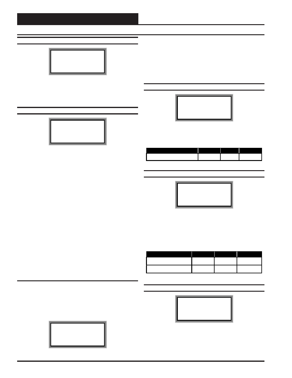
Setpoint Screen #1
MUA II Spts IDxxxx
Supply Air Temp
Setpoint.....: xxx
°
F
The Supply Air Setpoint is the desired temperature to be delivered by
the MUA II D at any time during the occupied mode of operation
Description
Minimum
Default
Maximum
Supply Air Temp Setpoint
50° F
70° F
90° F
Setpoint Screen #2
MUA II Spts IDxxxx
Staging Deadbands
Cooling....: xxx°F
Heating....: xxx°F
The Cooling Deadband added to the Supply Air Setpoint gives the
Cooling Mode Setpoint. When the Outside Air Temperature rises above
this setpoint, the MUA II D will go to Cooling Mode. The Heating
Deadband subtracted to the Supply Air Setpoint gives the Heating
Mode Setpoint. When the Outside Air Temperature drops below this
setpoint, the MUA II D will go to Heating Mode.
Description
Minimum
Default
Maximum
Cooling Deadband
2° F
5° F
20° F
Heating Deadband
2° F
5° F
20° F
Setpoint Screen #3
MUA II Spts IDxxxx
Unoccupied Deadbands
Cooling....: xxx°F
Heating....: xxx°F
The Uncoccupied Cooling Deadband added to the Supply Air Setpoint
gives the Unoccupied Cooling Mode Setpoint. When the Space Air
Temperature rises above this setpoint, the MUA II D will go to Unoc-
cupied Cooling Mode. The Unoccupied Heating Deadband subtracted