Assembly, Warning – Partner Formula 400 Chrome 2007 User Manual
Page 38
38
and magnitude of kickback and are recom-
mended. Your saw has a low kickback chain
and bar as original equipment. Repairs on a
chain brake should be made by an authorized
servicing dealer. Take your unit to the place of
purchase if purchased from a servicing dealer,
or to the nearest authorized master service
dealer.
S
Tip contact in some cases may cause a light-
ning fast reverse REACTION, kicking the
guide bar up and back toward the operator.
S
Pinching the saw chain along the top of the
guide bar may push the guide bar rapidly
back toward the operator.
S
Either of these reactions may cause you to
lose control of the saw which could result in
serious injury. Do not rely exclusively upon
the safety devices built into your saw.
CHAIN BRAKE
S
Chain brake, designed to stop the chain in
the event of kickback.
WARNING
: Your chain saw is
equipped with a chain brake that is designed to
stop the chain immediately if you get a kick-
back. The chain brake reduces the risk of acci-
dents, but only you can prevent them. DO NOT
ASSUME THAT THE CHAIN BRAKE WILL
PROTECT YOU IN THE EVENT OF A KICK-
BACK.
SAFETY NOTICE:
Exposure to vibrations
through prolonged use of gasoline powered
hand tools could cause blood vessel or nerve
damage in the fingers, hands, and joints of
people prone to circulation disorders or
abnormal swellings. Prolonged use in cold
weather has been linked to blood vessel
damage in otherwise healthy people. If
symptoms occur such as numbness, pain,
loss of strength, change in skin color or
texture, or loss of feeling in the fingers,
hands, or joints, discontinue the use of this
tool and seek medical attention. An
anti-vibration system does not guarantee the
avoidance of these problems. Users who
operate power tools on a continual and
regular basis must monitor closely their
physical condition and the condition of this
tool.
ASSEMBLY
Protective gloves (not provided) should be
worn during assembly.
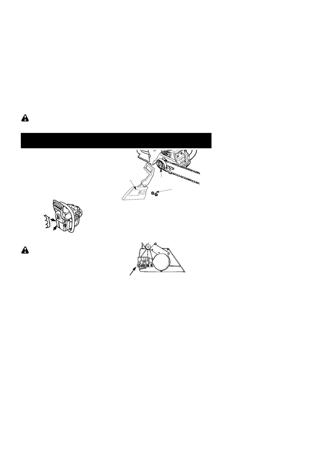
ATTACHING THE BUMPER
SPIKE
The bumper spike may be used as a pivot
when making a cut.
1. Loosen and remove the chain brake nuts
and the chain brake from the saw.
2. Attach the bumper spike with the two
screws as illustrated.
ATTACHING THE BAR & CHAIN
(If
not already attached)
WARNING
: Recheck each assem-
bly step if the saw is received assembled. Al-
ways wear gloves when handling the chain.
The chain is sharp and can cut you even
when it is not moving!
1. Loosen and remove the chain brake nuts
and the chain brake from the saw.
2. Remove the plastic shipping spacer (if
present).
Chain
Brake
Chain Brake
Nuts
Clutch Drum
3. An adjusting pin and screw is used to ad-
just the tension of the chain. It is very im-
portant when assembling the bar, that the
pin located on the adjusting screw aligns
into a hole in the bar. Turning the screw will
move the adjustment pin up and down the
screw. Locate this adjustment before you
begin mounting the bar onto the saw. See
illustration below.
Adjustment located on Chain Brake
Inside view of
Chain Brake
4. Turn the adjusting screw by hand coun-
terclockwise until the adjusting pin just
touches the stop. This should allow the
pin to be near the correct position.
5. Slide guide bar behind clutch drum until
guide bar stops against clutch drum
sprocket.