Installation guides – Posiflex PD-2600 User Manual
Page 3
Part 3
INSTALLATION GUIDES
HOST SYSTEM PREPARAION
For serial interface (RS232) PD-2601or PD-2602 or PD-2603 to be used in HT
or PB or KS or TP or FT series, you have to adjust during power off the
internal jumper of the host system to supply 5 V DC to the COM port selected
for the serial interface pole display. This adjustment has to be done by a
qualified electronic technician following guide from relevant technical manual.
The default communication protocol should be set to 9600 bps, none parity, 8
data bits, 1 stop bit with hardware handshaking on CTS. The power for the
USB interface type pole display is supported through the USB connection.
However, should these customer displays are to be connected through an USB
HUB instead of a direct USB port of the system, the HUB must be powered by
a separate power adaptor otherwise there could be the power shortage problem.
INSTALLING PD-2600
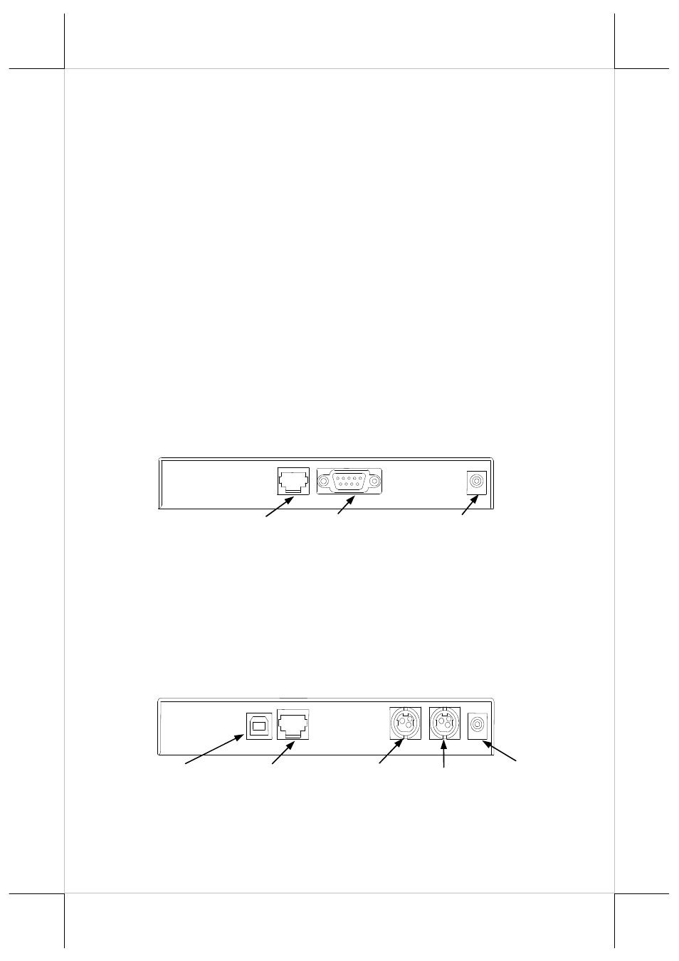
In base of stand alone models (PD-2600 models only), looking from rear side
of the bottom, the connector area will look like below:
For serial (RS232) interface models:
The RJ45 type modular connector is for internal use and is already occupied.
The RS232 input port is a DB9 female connector. Connect the attached RS-
232 signal cable to this port and one of the COM port in the host system. Set
the RS-232 communication protocol for this port to 9600 bps, no parity, 8 bits,
1 stop bit with hardware handshaking. Connect the power adaptor to the
rightmost power connector. Turn on the switch in the front side of the base.
For USB interface models:
The RJ45 type modular connector is for internal use and is also already
occupied. Connect the “B” type connector of the interface cable to “USB” in
connector area and the “A” type end to USB port of the host. Insert the 2 pin or
To Display head
24 VDC 24 VDC
RS232 In
12 VAC In
12 VAC In
+24 V DC In
+24 V DC Out
To Display head
USB