Troubleshooting, Aec 200-4d direct connect spool gun wiring diagram, Testing information – Profax AEC 200-4D User Manual
Page 7: Figure 1
4
5
TESTING INFORMATION
1. Input Voltage
Red - Term. 1 & 2
24VAC
Primary power input to PC board.
2. Return Voltage
Red - Term. 1 & 3
24VAC w/trigger activated
24VAC return for contactor operation.
3. Potentiometer
Yellow - Term. 1 & 3
2.5K
Gives reference value to PC board for speed control.
Yellow - Term. 2 & 3
0 to 2.5K
Should give smooth reading 0 through 2.5K when
potentiometer is turned.
4. Motor
Blue - Term. 1 & 2
1 to 27VDC
DC power output to motor from PC board with
Resistance 4.0 ohms
reference to potentiometer setting.
5. Trigger Switch
White - Term. 1 & 3
Norm. Closed
Brakes motor when trigger is released. Opens to
release brake when trigger is activated.
White - Term. 2 & 4
Norm. Open
Closes when trigger is activated completing circuit
to motor. Also completes circuit from P1 - Term. 4
to P1 - Term. 5 for power source contactor activation.
TEST ITEM
TEST POINT
VALUE READING
DESCRIPTION
TROUBLESHOOTING
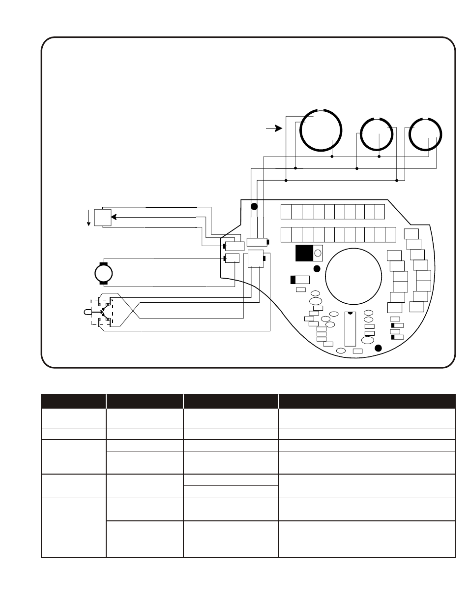
Figure 1
AEC 200-4D DIRECT CONNECT SPOOL GUN WIRING DIAGRAM
Min.
NO
NO
NC
NC
14
15
13
WHITE
WHITE
YELLOW
2.5K
POT
D9
D10
R15
D11
R14
C38
R12
R13
R11
C36
C37
R9
R10
R7
R6
R5
R3
R4
C44
C43
R1
C1
C3
C5
C7
C9
C11 C12 C15 C17 C19
C2
C4
C6
C8
C10 C12 C14 C16 C18 C20 C21
C22
C23
C25
C27
C29
C31
C33
C34
C35
C32
C30
C28
C26
C24
R8
C39
C44
C40
C42
M
CW
YELLOW
B
A
J
K
I
C
G
D
E
F
M
L
H
N
A
E
K
F
D
G
H
B
C
J
B
C
A
E
F
H I
D
G
J
Comparc, Miller
Powcon,Thermal Arc
14 Pin
Miller
10 Pin
(MM250X)
only
PROFAX
10 Pin
(P250SG & P300SG)
only
REAR VIEWS
Std.
AEC 200-4DM
Opt.
AEC 200-4DMX
Opt.
AEC 200-DP
U2
Trigger
(shown off)
Motor
Speed
Control
U1
1 2 3
1 2
3 2 1
4 2
3 1
RED
BLACK
Red
White
Yellow
Blue
BLACK
WHITE
GREEN
3123
.023
Hard .031
3356
.030-.035
Hard .044
3299
.045-3/64”
Alum. .060
3300
1/16”
Alum. .078
45-070
3/64”
Alum. .073
3793
.030-.035
Hard .040
3839
.045
Hard .053
3150
.030-.035
Hard .040
3223
.045
Hard .053
3455
3/64”
Alum. .061
3456
1/16”
Alum. .081
3067
.030-.035
Hard .060
3068
.045-3/64”
Alum. .084
3069
1/16”
Alum. .120
3136
.030
Alum. .040
3115
.035-.047
Alum. .064
3135
1/16”
Alum. .084
4552
9/16”
Brass
4270
11/16”
Brass
4269
11/16”
Brass
4572
11/16”
Copper
4268
7/16”
Brass
PART NO. WIRE SIZE
I.D.
4”
6-1/8”
4”
1-5/8”
1-27/32”
1-5/8”
1-1/2”
1-1/2”
1-5/8”
1/4”
1/4”
1/4”
1/4”
1”
1”
1”
1”
1”
1/4”
1/4 - 20 Thd.
1/4 - 20 Thd.
1 - 14 Thd.
7/8 - 14 Thd.
7/8 - 14 Thd.
7/8 - 14 Thd.
7/8 - 14 Thd.
PART NO.
I.D.
MATERIAL
NO. PART NO. DESCRIPTION
1
4119
Bent nozzle kit
2
4346
Nut
3
4137
Nozzle
4
4300
Slip ring
NO. PART NO. DESCRIPTION
1
4638
New style assembly
2
4268
Nozzle
3
4269
Nozzle
NO. PART NO. DESCRIPTION
1
4124
Old style assembly
2
4105
Adapter
3
4108
Barrel
NO. PART NO. DESCRIPTION
1
4925
Flexible barrel
2
4580
Tip holder
(included)
NO. PART NO. DESCRIPTION
5
4139
Adapter
6
4108
Barrel
7
4138
Assembly (5 & 6)
NO. PART NO. DESCRIPTION
4
4147
Nozzle body
5
4641
Spacer
6
4640
Adapter sleeve
NO. PART NO. DESCRIPTION
4
4117
1/2” nozzle
4118
3/4” nozzle
4110
5/8” nozzle
NO. PART NO.
DESCRIPTION
3
9635-8¼
Liner (cut to length)
Included
2
4
2
3
4
1
2
3
4
2
5
3
6
3
5
6
Note: Additional 4137 nozzle included
1
1
1
1-1/2”
10-3/4”