Aec 200-4c specifications, Warning, Preweld check list – Profax AEC 200-4C User Manual
Page 4: Shutting down, Maintenance
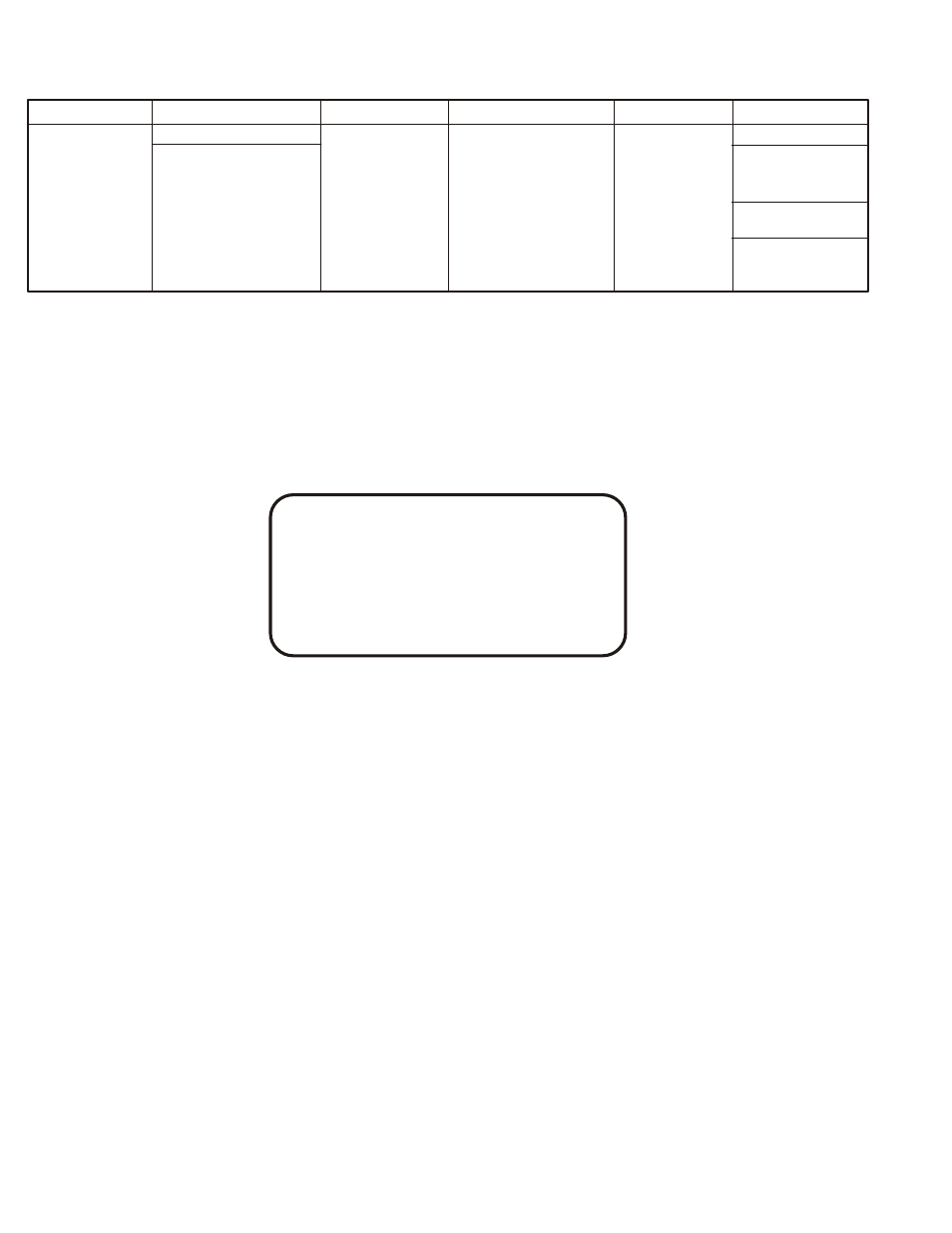
AEC 200-4C SPECIFICATIONS
Input Power
Weld Output Rating
Wire Capacity
Wire Speed Range
Dimensions
Weight
Argon or Helium
Gun & Cables
250 Amps
.023 in. through
Net 26 lbs.
115VAC
50% Duty Cycle
1/16" Aluminum
30 IPM
Height 8.25"
Ship 29 lbs.
50/60 Hz.
200 Amps
or
to
Width 3"
100% Duty Cycle
.023 in. through
800 IPM
Length 15"
4C Control
.045 Hard Wire
Net 7.5 lbs.
Ship 9 lbs.
The AEC 200-4 Spoolgun and AEC 200-4C control are interfaced together to give the improved SOLID STATE
motor control performance to the Classic AEC 200 Spoolgun design. This system can be connected to any
adequately sized CONSTANT VOLTAGE welding power source that provides 115V or 24V AC 50/60 Hz. auxiliary
power and will operate 115 volt feedback or contact closure contactor circuits.
INSTALLATION (For help see fig. 2)
WARNING!
DISCONNECT ALL ELECTRICAL POWER TO
THE WELDING POWER SOURCE BEFORE
INSTALLING THIS EQUIPMENT
1. Connect the two conductor contactor cord to the contactor receptacle of the welding power source.
(See “Note” at bottom of page)
2. Connect the AEC 200-4 Spoolgun as follows:
A. Weld cable to the POSITIVE (+) terminal of the welding power source.
B. Gas hose to the flowmeter/regulator at the gas supply.
C. Control cable to the receptacle on the front of the AEC 200-4C control box.
3. Connect the three conductor power cord to a 115 Volt 50/60 Hz. power source.
(This control can also be connected to a 24 Volt AC power source. Contact the “PROFAX” technical service department if this is prefer red.)
NOTE!
The AEC 200-4C control box is shipped with the contactor control cord connected to terminals 1 & 2 on “TS1”
terminal strip. This is for use with welding power sources requiring a normally open set of contacts to operate the
contactor.
Power sources requiring 115 volt AC for contactor operation: (For help see fig.3)
A. Remove the control box cover.
B. Locate the four terminal strip “TS1”. Move the black and white wires from terminals 1 and 2 to
terminals 3 and 4. (color of wire to terminal does not matter)
C. Install the top cover and secure.
FIGURE 2
CONSTANT VOLTAGE POWER SOURCE WITH THE AEC 200-4C GUN & CONTROL
PREWELD CHECK LIST
A.) Make sure the AEC 200-4 Spoolgun is set up for wire size selected with, proper liner, contact tube and nozzle.
B.) All control cable and hose connections are tight.
C.) Mig wire installed for counter clockwise feed-off.
D.) Proper shielding gas and flow selected and cylinder turned on and valve backseated.
E.) Power source on and set for required voltage.
F.) Welding wire extended from end of nozzle.
NOTE: We recommend using scrap metal for trial welds and adjusting gun speed, amps and voltage before your welding operation. This will
familiarize you with the Spoolgun's operative characteristics.
SHUTTING DOWN
After your welding job is complete or work is stopped for any appreciable time proceed as follows:
A.) Turn power source off.
B.) Disconnect 115VAC to the control box if separate from power source.
C.) Turn shielding gas off.
D.) Make sure cover is secured on spoolgun.
MAINTENANCE
NOTE: Before performing any maintenance on spoolgun, BE SURE all sources of power are TURNED OFF.
It is important to periodically inspect and clean if necessar y the AEC 200-4 Spoolgun. Inspect as follows:
1.) Inspect cable/hose assembly, (power cords, control cables & gas hose) for frayed or cracked insulation. Damaged wires and cables
are hazardous to your health and should be repaired or replaced immediately.
2.) Look for and clean if necessary any grease or grime from spoolgun. Grease containing metallic par ticles can cause short circuits.
3.) Check all mounting screws and nuts for tightness.
4.) Front cover should be in place during any welding operation. This keeps weld spatter from causing short circuits.
3
2
115 VOLT AC
POWER CABLE
115 VOLT AC
*PLUG NOT INCLUDED
CONTACTOR CONTROL
CABLE TO CONTACTOR
CONTROL RECEPTACLE
ON POWER SOURCE
(see installation instructions)
POWER
SOURCE
HOSE TO GAS
SUPPLY
CONNECTION
BLOCK
CABLE
BOOT
GAS
CYLINDER
POSITIVE
OUTPUT
TERMINAL
WELDING CABLE TO
POSITIVE OUTPUT TERMINAL
ON POWER SOURCE
MODEL
AEC 200-4C
CONTROL
MODEL
AEC 200-4
SPOOL GUN
GAS & WELDING
CABLE
WELDING CABLE FROM
NEGATIVE OUTPUT TERMINAL
ON POWER SOURCE
WORK
MULTI CONDUCTOR
CABLE TO TERMINAL
STRIP IN CONTROL BOX