Protech, Installation, Circuit description – Protech Audio 66708 User Manual
Page 2: External connections
INSTALLATION
Page 2
The Model 66708 is designed to mount in a standard 19" EIA
rack. The unit should be mounted in the bottom of the rack. A
minimum of a one rack space ventilation panel should be
mounted directly above the power supply, to provide adequate
ventilation.
Check that the AC line voltage and amperage rating are correct
before connecting the line cord. The rating should be 120VAC,
with at least 3 amperes of current available.
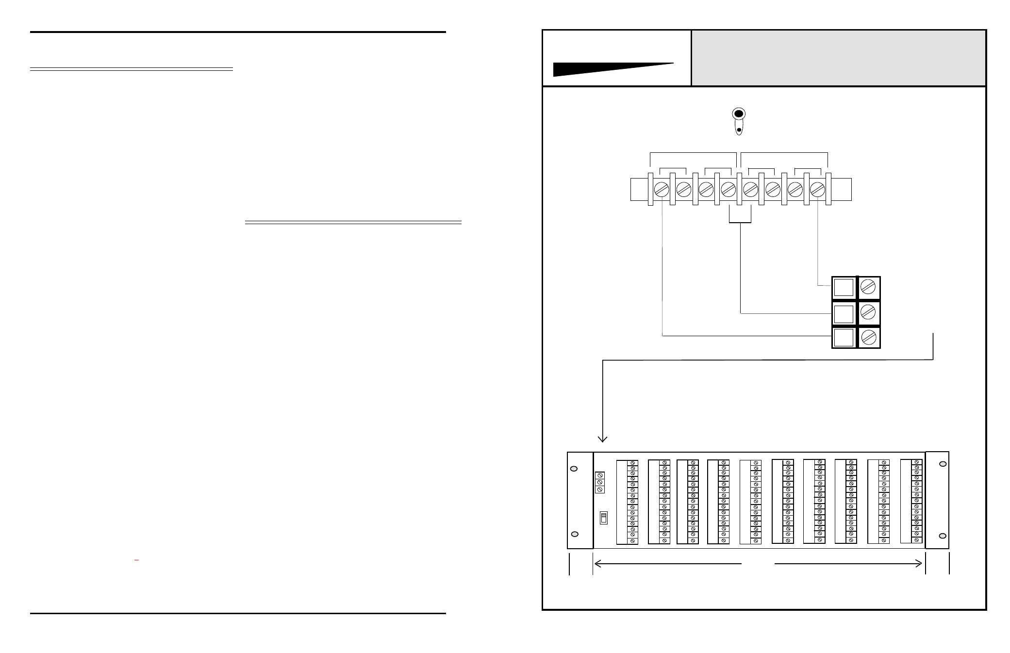
The DC connections should be made using a minimum of
18AWG wire. In the local sensing mode, three conductors will
be necessary. In the remote sensing mode, seven conductors
will be required. The connections are made as indicated in
Figure 1. After making all connections from the power
supply to the load, turn on the unit, and using a voltmeter,
verify that the voltages and the polarity are correct at the load.
The output voltages are adjustable via potentiometers, which
are accessible at the rear of the power supply chassis.
The actual steps for installation for the Model 66708 Dual
Power Supply are as follows:
1 - Mount the Model 66708 into the lowest available position in
the rack.
2 - Mount a single rack space (minimum) ventilation panel in the
rack, immediately above the power supply.
3 - Check the AC receptacle for proper voltage and current
rating before connecting the line cord.
4 - Plug in the line cord, and turn unit on. The neon power
indicator in the on/off switch should illuminate. The two green
LED DC voltage indicators should illuminate.
5 - Turn unit off, and wire the outputs to the load, observing
connection points as indicated in figure 1.
6 - Turn unit on, and using a DC voltmeter, measure the DC
voltage at the load. In the bipolar configuration*, the voltage
between GROUND and +VDC should measure 18 volts DC
positive. The voltage between the GND and -V should
measure 18 volts DC negative. The voltages may be adjusted
by using the potentiometers that are mounted on the rear of
the power supply chassis.
*(ALL INTEGRA III SYSTEM
Amplifiers require +15-18VDC)
7 - Check the polarity of the voltage at the load. Between Pins
GND and +V, it should measure +18 volts. Between pins GND
and -V, the voltage should measure -18 volts.
Your installation is now complete. Continuous operation of the
Model 66708 is normal, and requires no further operations from
support technicians. There are no adjustments which must be
made on a periodic basis. However, periodic testing of the
overall system may be specified by the system designer.
CIRCUIT DESCRIPTION
The Model 66708 is a state of the art dual power supply. The
unit has two independent regulated outputs. Each output may
be used separately, or strapped together to form a bipolar
configuration. The bipolar arrangement is the type usually
used for the INTEGRA III SYSTEM.
The power transformer is toroidial in construction. This type of
power transformer emanates a much smaller AC field, which is
of great importance when working with low level audio ampli-
fiers. The secondary of the toroid has two separate windings,
one for each power supply output.
There are two separate rectifier/regulator circuits in each Model
66708. The rectifier is a standard full wave bridge rectifier
followed by two 4700uf filter capacitors. The voltage regula-
tion, and current sensing are derived by using an I.
C. regulator, the MC1723. The output current capability is
increased by the addition of 4 external pass transistors
(TIP120)
for each output.
NOTE: Power supply outputs are floating with re-
spect to chassis and earth ground.
PROTECH
OUTPUT #2
OUTPUT #1
MODEL 66708
®
1.5"
16.5"
*
REAR VIEW BACKPLANE/CARD FRAME ASSEMBLY
*
*
*
*
*
*
*
*
*
GND ON
GND
LIFT
10
9
8
7
6
5
4
3
2
1
*Space used for additional connectors or trimpots as needed for application
1.5"
GND
V+
V-
+18V
-18V
GND
DETAILED
VIEW OF
POWER
CONNECTOR
BELOW
CONNECTION DIAGRAM FOR MODEL 66708
TO BE USED WITH
857B
CARD FRAME.
Leave Factory Installed
Sensing Jumpers In Place,
Unless Remote Sensing Is
Required
NOTE:
EXTERNAL CONNECTIONS
SENSING
V+
V-
V-
SENSING
V+
Model 857B
Power Supply Output is floating with respect to ground. It may be
necessary, depending on the individual installation, to provide a
ground strap from the card frame “GND” pin to power supply
ground.
Ground