Protech, Installation, Alignment – Protech Audio 808B User Manual
Page 2
INSTALLATION
The 800 Series Preamplifiers and Line Amplifiers are
designed to be mounted in the Model 857B Card Frame Package
or the Model 858B Card Frame Package. The Model 857B Card
Frame Package will accomodate up to 10 audio cards, and
requires an external power supply, Model 66708.
The Model 858B Card Frame Package will accomodate up to 9
audio cards, and has a built-in, unpluggable power supply card.
Both card frame assemblies buss the DC power to the individual
card slots, and provide screw-type barrier termination points for
audio and DC connections.
After receiving an order for 800 audio cards, and prior to
shipping the order, the factory has requested from you or
your firm, a card file layout sketch. Using this drawing, the
factory has mounted the necessary trimpots in the backplane
assembly. This service allows the factory to test each card
in the card frame assembly, and saves the installer time when
assembling the complete audio system. Also, the installer can
be confident that each card received has been tested in the
actual slot used.
4- Unpack each individual card, inspect for shipping
damage, and assuming none is found, slide the card
half-way into the appropriate slot. After all cards have been
installed half-way into the card frame, plug in one card at a time
and turn on the power supply. Make sure no unusual loading is
noticed at the power supply. If loading is noticed, turn off the
power supply, unplug the card and recheck terminations. If no
loading is noticed, continue inserting each card in the card
frame, checking power supply loading as each card is plugged
in. When all the cards have been plugged in, the installation is
complete, and all that remains is the alignment.
Page 2
ALIGNMENT
The actual steps necessary for installation of the 800 Series
Microphone Preamplifier and Line Amplifier cards, are compa-
rable to those necessary for any of the 800 series cards. They
are as follows:
1- Mount the card frame in an appropriate EIA 19" width rack,
using 4 screws of sufficient tensile strength to provide secure
mounting.
2- A determination has been made as to which type of power
supply will be used on your system. Follow the instructions for
the type of power supply you will be installing.
EXTERNAL POWER SUPPLY. If an external power supply
is to be used, terminate the proper supply connections to
pins 1, 2, & 3 of the DC barrier connector, as shown in the card
frame layout drawing. Turn on the power supply, and using
a DC voltmeter, check for correct voltage and polarity at pins 1,
2, & 3 of the barrier connector.
INTERNAL POWER SUPPLY. If a plug-in power supply card
is to be used, plug in the supply card, turn it on, and check for
proper illumination of the positive and negative voltage LED's,
on the front of the power supply card.
3- Terminate all audio input and output connections, using
the card connection drawing on page 3. Double conductor
shielded cable is recommended for all audio connections.
Terminate each unused input with a 1K ohm resistor.
Each 800 Series card with microphone level inputs has been
shipped from the factory aligned for 45dB of gain. Each Line
amplifier card has been shipped with the gain set for unity.
This alignment optimizes headroom. If additional gain is
required, the following alignment procedure is recommended;
1 - Apply a signal representative of the actual signal level to be
be used, to channel #1.
2 - While monitoring the ouput channel, turn the output gain
gain trimpot clockwise until the output signal reaches the
desired level. .
3 - Repeat steps 1 and 2 for each channel on your
preamplifier or line amplifier.
This completes the installation and alignment of your 800 Series
Limiter/Preamplifiers and Line Amplifiers. The cards may be
expected to deliver years of uninterrupted service.
Note 1-
The alignment procedures for 800 Series cards, differ from
card type to card type. Therefore it is necessary to consult the
alignment procedure for each type of card being installed, to
properly align a card frame using different card types.
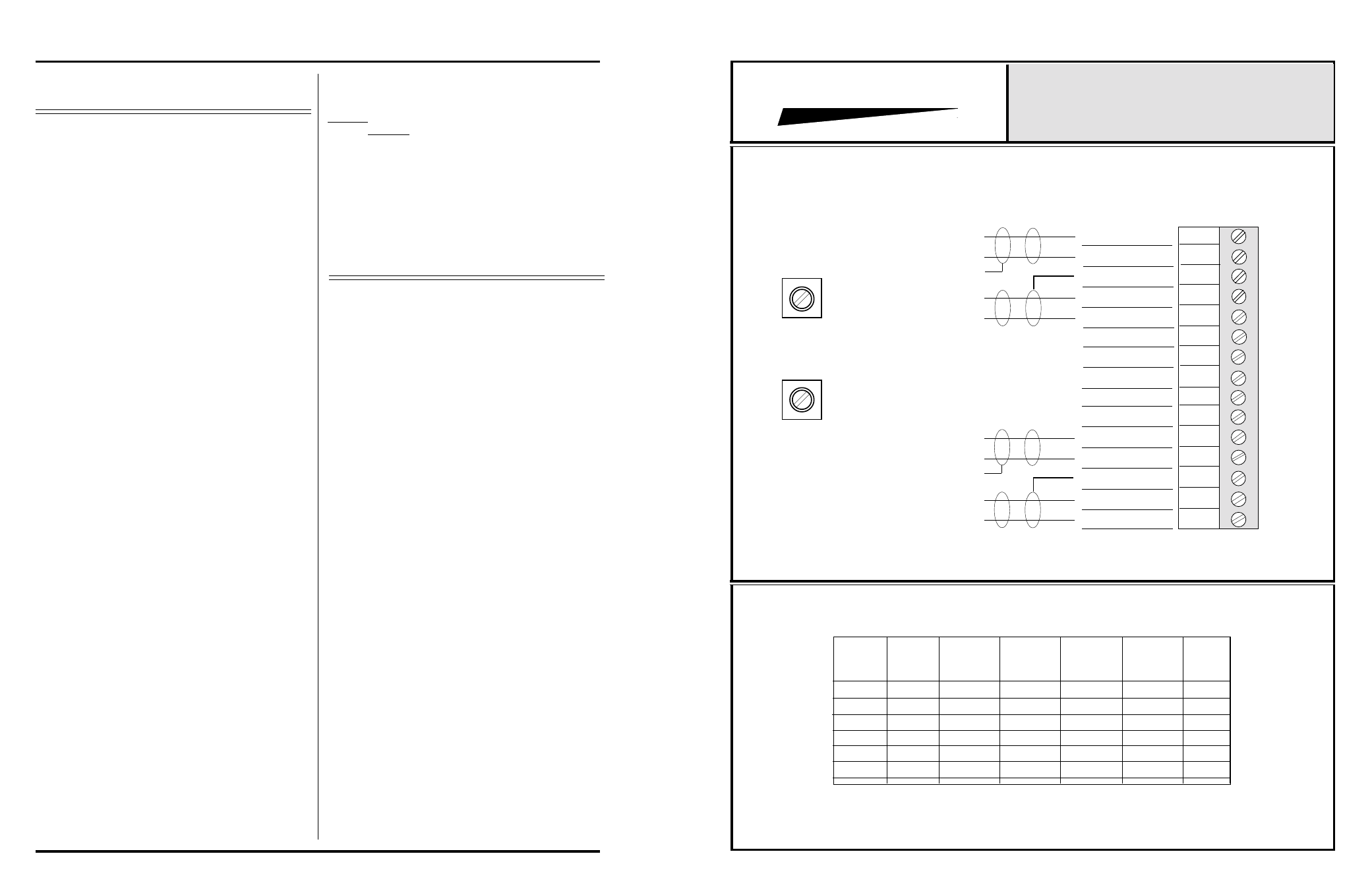
INTEGRA III SYSTEM
CONNECTOR & TRIMPOT DRAWING
MODELS 806B Through 816B
PROTECH
®
GROUND
1
2
3
4
5
6
7
8
9
10
11
12
13
14
15
GROUND
INPUT #2 HI
INPUT #2 LO
OUTPUT #2 HI
OUTPUT #2 LO
GROUND
L
H
H
L
INPUT #1 HI
INPUT #1 LO
OUTPUT #1 HI
OUTPUT #1 LO
Channel #1 Gain
Channel #2 Gain
857B & 858B BACKPLANE
CONNECTIONS
L
H
H
L
Channels
600 Ohm
Transformer
Input
150 Ohm
Transformer
Input
10K Ohm
Transformer
Input
17-52dB
Gain
-10 To
25dB
Gain
Model
Number
806B
807B
808B
814B
815B
816B
1
1
1
2
2
2
*
*
*
*
*
*
*
*
*
*
*
*