Protech Audio 891 User Manual
Protech
MODELS COVERED
INTEGRA III SYSTEM
The overall attenuation range of the VCA cards may be
modified in the field, by using a series resistor and changing the
value of the remote potentiometer.
The input sections are followed by a summing amplifier, on
mixing units, and then by a line amplifier circuit (on all models)
depending on the model selected. The output section is
transformer isolated with a high quality, 600 ohm line
transformer.
All units may be linked together to create larger mixing
networks. Both the audio output, and the link output may be
strapped for PRE or POST VCA. This feature allows the audio
output level to be remotely controlled, while the link output is
fed to other units at full volume, or the link output level may be
post VCA while the main output remains at full volume. This
PRE/POST VCA feature is particularly useful when logging
recorders are used.
Both models are designed to mount in the Models 857B or the
858B Card Frame Packages. The all VCA units may be mixed
or matched with other INTEGRA III SYSTEM cards to create
a complete audio system. The Model 858B will allow mount-
ing of 9 cards and an internal power supply. The Model 857B
will allow mounting of up to 10 cards with an external power
supply.
The Models 891 to 898 Remote Controlled Audio Cards are
designed to operate with either microphone or line level
input signals, with remote volume control, and are intended
for use in professional audio systems.
Typical applications are public address systems, court-
rooms, sales presentation rooms, headphone listening
systems, and recording systems. The actual application of the
amplifiers is found in buildings such as airports, factories,
courthouses, casinos, convention centers, libraries, hotels,
racetracks, training systems, corporate boardrooms, etc.
The models 891, 892, 893, and 894 have line level inputs.
The models 895, 896, 897, and 898 have microphone
level inputs. All inputs are transformer isolated. The gain of
each input stage is adjustable via a trimpot mounted on the
backplane assembly. The gain adjustment is independent of
the attenuation adjustment.
The attenuation is accomplished using an on-board VCA
(voltage controlled amplifier) circuit in each input section.
The VCA is controlled via a 0-5 volt DC control signal,
generated on-board, which is adjusted by a remotely mount-
ed 10K linear potentiometer. The default for the attenuation
is zero volts = zero attenuation. This default prevents loss of
signal if the control wires are accidentally cut.
PROTECH
®
891
892
893
894
INSTALLATION & OPERATION MANUAL
MODEL 891 - 898
REMOTE CONTROLLED AUDIO CARDS
www.
protechaudio
.com
INTEGRA III SYSTEM
PROTECH
®
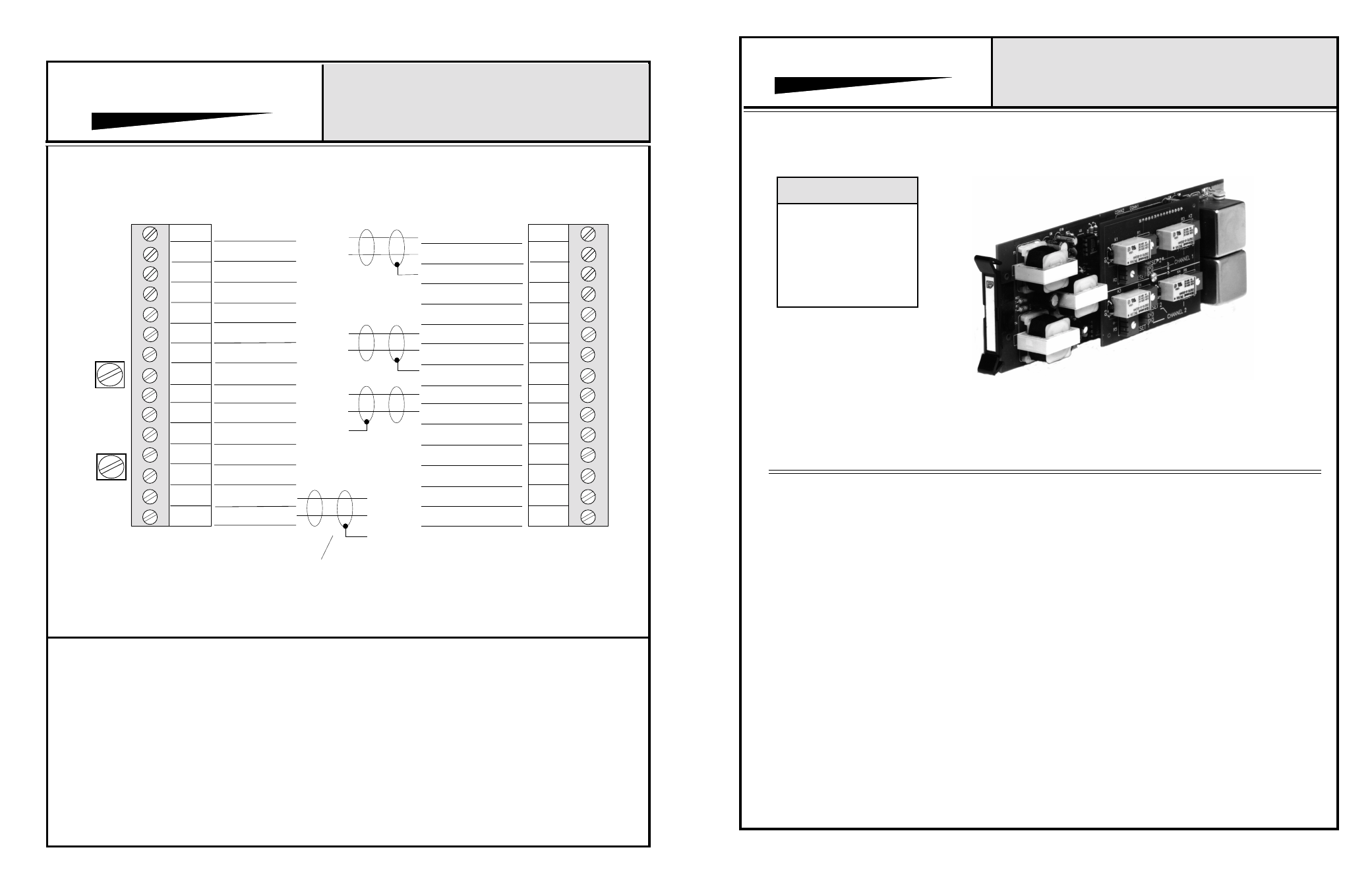
CONNECTOR & TRIMPOT DRAWING
MODELS 892, 893, 894, 896, 897, 898
NOTES:
1
2
3
4
5
6
7
8
9
10
11
12
13
14
15
INPUT #1 HI
INPUT #1 LO
SHIELD
H
L
POTS (2) HI
POT #1 ARM
SHIELD
LINK OUT
16
17
18
19
20
21
22
23
24
25
26
27
28
29
30
OUTPUT #1 HI
OUTPUT #2 HI
OUTPUT #1 LO
OUTPUT #2 LO
L
H
POT #2 ARM
POTS (2) LO
TYPICAL OF EACH OUTPUT
INPUT #2 HI
INPUT #2 LO
H
L
CH #2
GAIN
CH #1
GAIN
857B & 858B Backplane Connections
SUMMED OUTPUT
HI
SUMMED OUTPUT
LO
H
L
895*
896*
897*
898*
*Microphone Level Inputs
Model 894A Shown
1/06
Protech Audio Corporation, PO Box 597, 192 Cedar River Road, Indian Lake, New York, 12842, Voice 518-648-6410 Fax 518-648-6395