Protech, Installation, Alignment – Protech Audio 862B User Manual
Page 2
INSTALLATION
The 800 Series Audio Distribution Amplifiers are designed to
be mounted in the Model 857B Card Frame Package, or the
Model 858B Card Frame Package.
The Model 857B Card Frame Package will accomodate up to 10
audio cards, and requires an external power supply(Model
66708). The Model 858B Card Frame Package will accomodate
up to 9 audio cards, and has a built-in, unpluggable power
supply card.
The determination as to which backplane assembly to use in
your project, was made prior to our factory receiving the order.
The backplane assembly you have received will accommodate
the group of cards you or your designer have specified.
Page 2
The actual steps necessary for installation of the 800 Series
Microphone Preamplifier and Line Amplifier cards, are compa-
rable to those necessary for any of the 800 series cards. They are
as follows:
1 - Mount the card frame in an appropriate EIA 10" width rack,
using 4 screws of sufficient tensile strength to provide secure
mounting.
2 - A determination has been made as to which type of power
supply will be used on your system. Follow the instructions for
the type of power supply you will be installing.
EXTERNAL POWER SUPPLY. If an external power supply
is to be used, terminate the proper supply connections to pins 1,
2, & 3 of the DC barrier connector, as shown in the card frame
layout drawing. Turn on the power supply, and using a DC
voltmeter, check for correct voltage and polarity at pins 1,2 &
3 of the barrier connector.
INTERNAL POWER SUPPLY. If a plug-in power supply card
is to be used, plug in the supply card, and check for proper
illumination of the both the positive and negatrive voltage
LED's, on the power supply card front panel.
3 - Terminate all audio input and output connections, using the
card connection drawing on the facing page. Double conductor
shielded cable is recommended for all audio connections..
Terminate each unused input with a 1K ohm resistor.
ALIGNMENT
4- Unpack each individual card, inspect for shipping
damage, and assuming none is found, slide the card
half-way into the appropriate slot. After all cards have been
installed half-way into the card frame, plug in one card at a time
and turn on the power supply. Make sure no unusual loading is
indicated at the power supply . If loading is noticed, turn off
the power supply, unplug the card and recheck terminations.
If no loading is noticed, continue inserting each card in the card
frame, checking power supply loading as each card is plugged
in. When all the cards have been plugged in, the installation
is complete, and all that remains is the alignment.
Each 800 Series card with line level inputs has been shipped
from the factory aligned for unity gain. The units with
microphone level inputs is aligned for 45dB of gain. This
alignment optimizes headroom. If additional gain is required,
the following alignment procedure is recommended:
1- For microphone level input units that require phantom
power, unplug the red phantom power jumper, and push it on
both pins of the 2 pin phantom power terminal strip. This will
apply 15 volts DC phantom power to the input.
2- Apply a signal representative of the actual signal level to
be used, to the input.
3- While monitoring the #1 output channel, turn the output
#1gain trimpot, clockwise, until the output signal reaches
the desired level.
4- Repeat step #3 for each output on your distribution amplifier.
For any unused output, leave the gain trimpot in the maxi-
mum counterclockwise position.
This completes the installation and alignment of your 800 Series
Audio Distribution amplifiers. The cards may be expected to
deliver years of uninterrupted service.
Note #1-
The alignment procedure outlined above will almost always
provide the desired output level. However, when an unusually
low input signal level is present (less than -20dB), the installer
may wish to use the additional gain available in the input gain
stage. This gain should be used only when each output has
already been adjusted to the maximum gain setting. Using this
gain in systems which do not require in excess of 20dB of gain,
will result in reduced headroom.
Note #2-
The alignment procedures for 800 Series cards, differ from card
type to card type. Therefore it is necessary to consult the
alignment procedure for each type of card being installed, to
properly align a card frame using different card types.
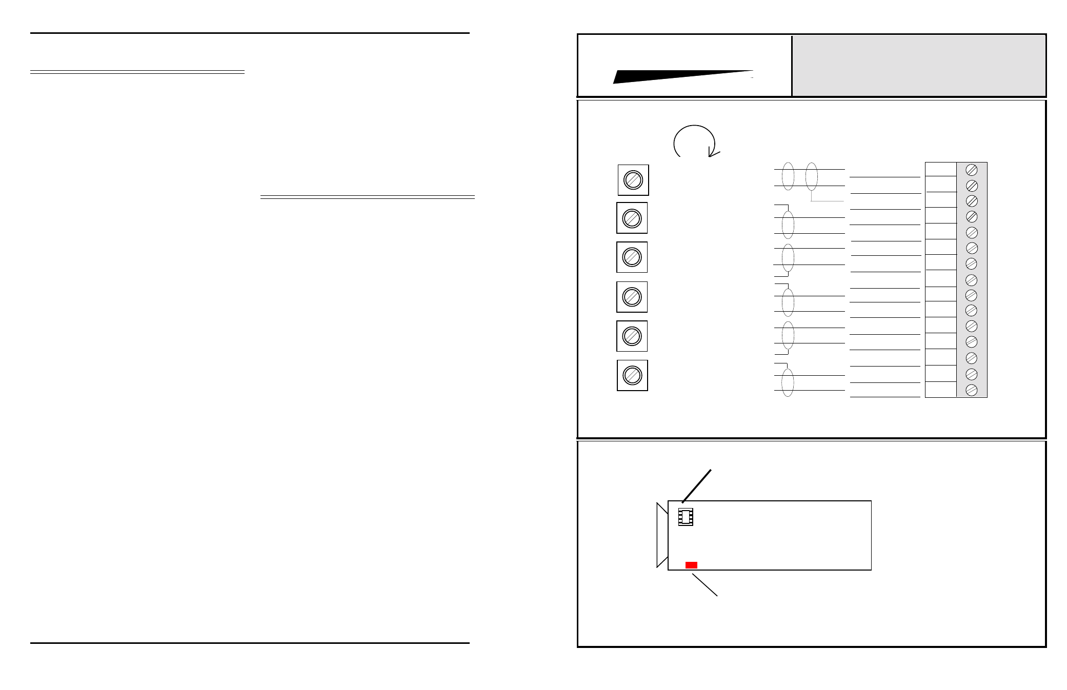
INTEGRA III SYSTEM
CONNECTOR & TRIMPOT DRAWING
MODELS 862B Through 865B
NOTE: For Link Capability On Models 862B 863B and 864B, Strap Pins 14 Together,
and remove IC from socket nearest card handle, on unit to be used as slave.
PROTECH
®
GROUND
1
2
3
4
5
6
7
8
9
10
11
12
13
14
15
OUT #2 HI
OUT #2 LO
GROUND
OUT #3 HI
OUT #3 LO
OUT #4 HI
OUT #4 LO
OUT #5 HI
OUT #5 LO
GROUND
H
L
H
H
L
H
L
L
L
H
H
L
INPUT HI
INPUT LO
OUT #1 HI
OUT #1 LO
S
S
S
S
S
MORE GAIN
CW
OUTPUT #5 GAIN
OUTPUT #4 GAIN
OUTPUT #3 GAIN
OUTPUT #2 GAIN
(10K)
(10K)
(10K)
(10K)
(10K)
(10K)
OUTPUT #1 GAIN
INPUT GAIN
857B & 858B BACKPLANE CONNECTIONS
Phantom power Jumper
Location of IC to be removed when
linking cards. Remove IC on all
“SLAVE” cards.