Protech Audio 5126 User Manual
Protech, Output configurations
Protech Audio Corporation PO Box 597, 192 Cedar River Road Indian Lake New York 12842 Voice 518-648-6410 Fax 518-648-6395
PROTECH
®
INSTALLATION & OPERATION
MANUAL
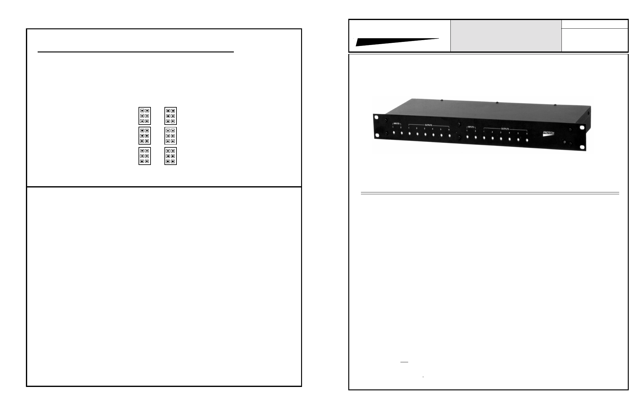
AUDIO DISTRIBUTION AMPLIFIERS
MODELS COVERED
5226
5226T
5126
5126T
Electronic or Transformer Balanced Inputs and Outputs.
All Inputs and Outputs Individually Adjustable.
The Models 5126, 5126T, 5226, 5226T audio
distribution amplifiers are designed for use
in professional audio systems.
The application of the ADA's is found in public
address systems, communication systems, back-
ground music systems, recording systems. and
broadcast systems.
Each of the four models offers two (2) inputs
and six (6) output configurations. The 5226 and
5226T offer two identical 2x6 sections.
The Models 5126 and 5226 have state-of-the-art
electronically balanced inputs and outputs. The
5126T and 5226T have transformer isolated
inputs and outputs.
The #1 input gain stage on all four models is
adjustable from -15 to 20dB of gain. The input two
gain stage is adjustable from 0 to 20 dB of gain.
This input serves as a reference level for unity
gain, when turned completely down. Each of the
outputs has independently adjustable gain, from
infinity to 20dB of gain. Adjusting the input stage
level will effect all of the output level settings
in that section. The 20dB of gain available
at the input stage should be used before the gain
of the output section is utilized.
Each output may be strapped, via an internal
push-on jumper, to provide the input 1 signal, or,
the input two signal, or, the sum of input 1 and
2. As shipped from the factory, all outputs are
strapped to provide both the 1 and two inputs.
The power supply section of all four models has
been designed to achieve the lowest possible
noise and hum specifications. The AC transformer
is a UL recognized wall mount unit. Designing
the transformer in this manner eliminates the AC
field inside the chassis, and results in greatly
improved noise and hum figures.
The power supply section also includes a rear
mounted fuseholder, a front mounted power on
indicator (green LED), and a ground lift switch.
The switch is used to disconnect the audio
amplifier ground from earth ground, if
necessary. In almost all systems, the units will
achieve best results with the ground lift switch
in the ON position.
Each of the four models requires only a single
unit of vertical rack space. The choice of single
or dual units provides extreme circuit density in
a minimum of rack space.
1/06
OUTPUT CONFIGURATIONS
A1
A2
A1 & A2
Place Red Push-On Jumpers On Desired Configuration Pins.
Units are shipped from factory with all outputs in “A1 & A2” configuration.
Output 3
Output 2
Output 1
6
5
4
- Page 4 -
Notes: