Cam adjustments, Limb stop adjustments, Information on draw stop adjustments – PSE Archery Bow 2014 User Manual
Page 17: Compound bow, User’s guide
Compound Bow
USER’S GUIDE
PAGE
17
cam adjustments
wheels/cams:
Many PSE wheels and cams have adjustable features. Each one comes from
the factory set up and ready to use but there may be occasions that you need to adjust the
characteristics of your bow. In some cases you will need a PSE Tune chart to determine what
to adjust, and you may need to see a PSE Dealer for information. If you are not sure of the
adjustment you are making, stop and see your PSE Dealer for assistance. In some cases, an
appropriate bow press will be needed to make adjustments to cams and wheels. If you do not
have an appropriate press, see your PSE Dealer.
cam orientation:
On cams with orientation marks, a reference mark is found to indicate an approximate
orientation. This line is for reference only and is meant to give approximate orientation
only and may vary between bow models. The orientation of the cams may be changed slightly
by twisting or untwisting the string or cables.
all inner-cams:
The inner-cam system allows draw length adjustments over a prescribed range usually without
putting the bow in a bow press. There are two types of inner-cam systems: discrete setting
inner-cams and Posi-Lock inner-cams.
Discrete setting inner-cams have the adjustment screws going through a specific hole in the
inner-cam and threading into the cam. The screws need to be completely removed to make
adjustments. The “A” setting is the longest draw length for that bow and draw lengths get
shorter as you progress through the alphabet (A to B, B to c, etc.)
Posi-lock adjustable inner-cams are adjustable in ½” draw length increments. The “A” setting is
the longest setting for the cam. Draw lengths get shorter as you progress through the alphabet
(“A” to “B”, “B” to “c”, etc.) by roughly ½” per letter.
Second and third generation Posi-lock inner-cams
allow for draw length adjustments in ½” increments
without changing inner-cams. To adjust draw length,
loosen the two 8-32 button head screws two full
turns. This will allow the inner-cam to be lifted far
enough to disengage the positioning pin and allow
the inner-cam to rotate to a new position. Some
cams may require the 8-32 button head screws to
move to alternate locations to reach the new draw
length adjustment position. Some draw length
adjustment positions may not be accessible without
putting the bow in a bow press. When the new
draw length adjustment position has been achieved
with the inner-cam, tighten the two 8-32 button
head screws and move the draw stop to the
matching setting (“A” and “A”, “B” and “B”).
In cases where there is an inner-cam on both the top and bottom cam, both cams must be
set in the same letter position for the bow to tune and shoot properly. In cases where there
is a separate draw stop, the draw stop must be moved to the hole marked with the letter
corresponding to the inner-cam setting.
Positioning Pin
information on draw stop adjustments:
The position of the draw stop must match the setting on the inner-cam. For example, if the cam is set on “E”, the draw
stop must be placed in one of the draw stop holes marked with an “E”. If the inner-cam is in the “B” setting, the stop
must be in the “B” position. certain hybrid cams have top and bottom stops. They can be shot with both stops for a
harder “wall” or with only the top stop for a softer “wall”. Never shoot hybrid cams with the two stop option with only the
bottom stop. In either case, the stops need to be in the holes marked with the same marking as the inner-cam setting.
Draw Stop
Draw Stop
Screw
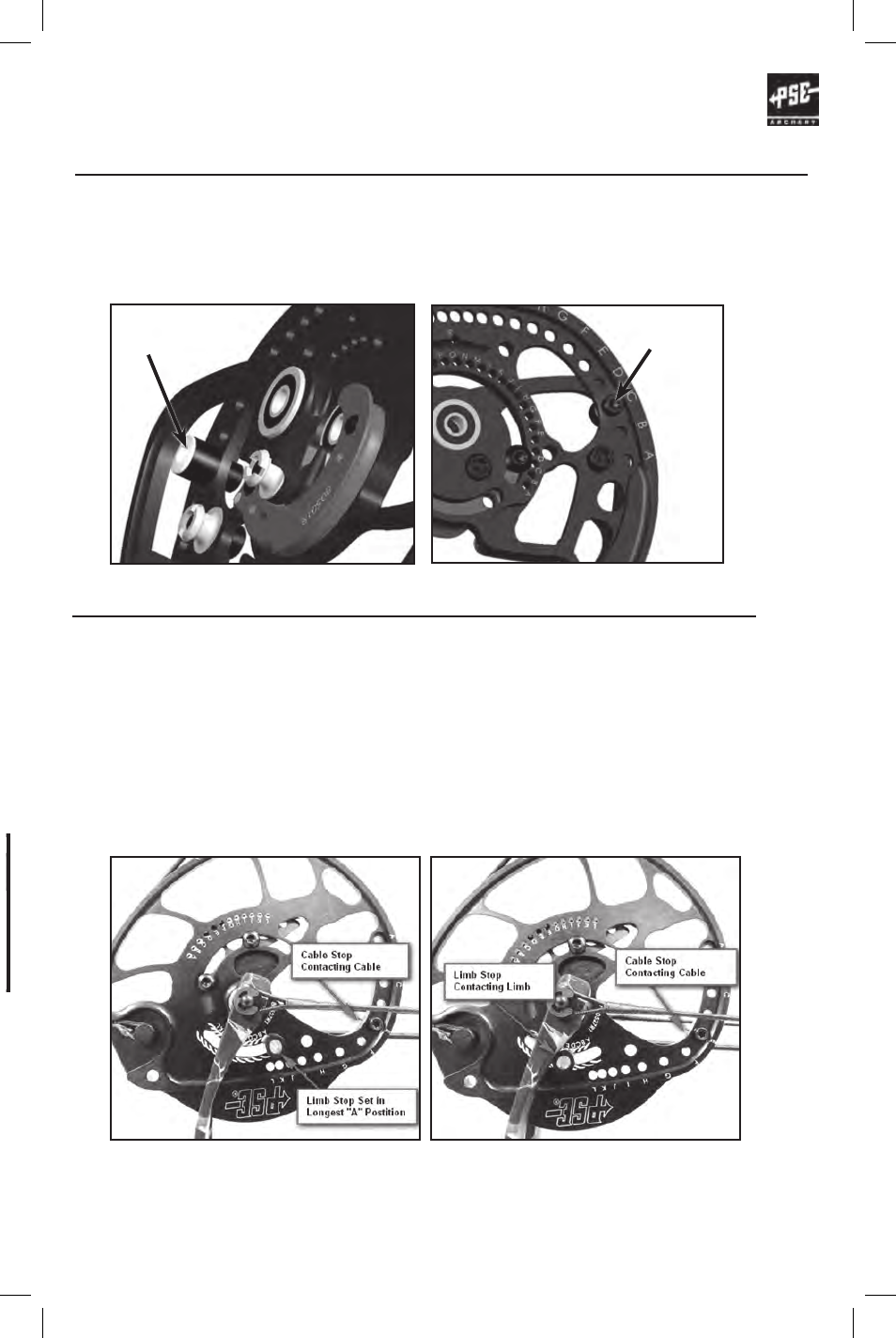
limb stop adjustments
On bows equipped with a limb stop and cable stop, use of the limb stop is optional. If
choosing not to use the limb stop it may be removed or set in the longest “A” position so
that it does not contact the limb before the cable stop. Engraving for limb stop positions is
approximate and for reference only. Many factors will cause changes to the optimum limb
stop position.
OPTION 1: (If a safe method of holding the bow at full draw is available) Set Limb Stop to
the Longest “A” Location and time bow to cable stops at desired draw length as shown in
Figure 1. Using a safe method to hold the bow at full draw adjust limb stop so it contacts
the limb as shown in Figure 2.
OPTION 2: Set Limb Stop to the Longest “A” Postition. Time bow to cable stops at desired
draw length.Set Limb stop to the corresponding stop position. Draw bow with an arrow and
observe whether the cable stop or Limb Stop contacts first. Make small adjustments to the
Limb Stop position and recheck until it contacts at
the same time as the cable stop.
FIGURE 2
FIGURE 1
8-32 Button Head Screw