Randall Amplifiers RG3003H User Manual
Page 2
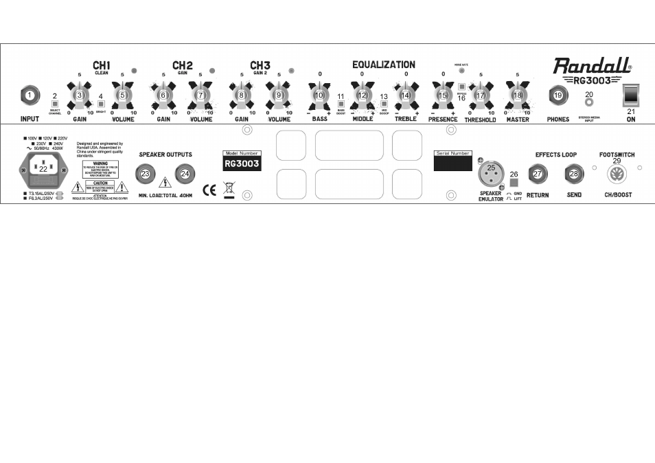
1. 1/4” Guitar Input.
2. Channel selector switch toggles between 3 channels (footswitchable).
3. Channel 1 gain controls amount of pre amp drive to channel 1.
4. Bright switch adds Hi-Frequency EQ “Sparkle” to Channel 1.
5. Channel 1 volume controls the amount of Channel 1 signal being sent to the master volume
output.
6. Channel 2 gain controls amount of pre amp overdrive to channel 2 - this will control the amount of
“distortion”.
7. Channel 2 volume controls the amount of Channel 2 signal being sent to the master volume
output.
8. Channel 3 gain controls amount of preamp overdrive to channel 3 - this will control the amount of
“searing distortion”.
9. Channel 3 volume controls the amount of Channel 3 signal being sent to the master volume
output.
10. The Bass knob controls the amount of low frequency equalization for the entire signal.
11. The BASS BOOST will enhance low EQ - Warning: use of boost with the Bass knob turned up
can cause speaker damage.
12. The Middle knob controls the mid-frequency equalization for the entire signal.
13. The MID SCOOP will decrease middle EQ similar to a “smiley face” setting on a graphic EQ.
14. The Treble knob will control the amount of High frequency equalization for the entire signal.
15. The Presence knob controls the uppermost High EQ frequencies above the Treble EQ shelf.
16. NOISE GATE BYPASS removes the noise suppression circuit from the signal path.
17. THRESHOLD controls the Noise Reduction function. After setting your preferred gain and tone
settings, play your guitar very softly and turn up the threshold until it begins to eliminate the
softest notes then turn it slightly under that “threshold”.
17. THRESHOLD controls the Noise Reduction function. After setting your preferred gain and tone
settings, play your guitar very softly and turn up the threshold until it begins to eliminate the
Congratulations on the purchase of your new RANDALL Amplifier! We at Randall Amplification appreciate that you chose the RG3003H Amplifier and wish you
years of great tone and enjoyable playing time. Please review the safety instructions below and be aware that the documentation provided in this manual references
120volt USA versions of the models covered. Note that the POWER listed on the back of the unit should be for your countries’ power standard.
18. The MASTER VOLUME controls the amps volume going to whatever speaker cabinet is
connected.
19. The PHONES output allows for headphones to be plugged in - Note: speaker out is
muted during headphone operation.
20. STEREO MEDIA INPUT allows for 1/8” media source such as MP3 player to be inserted
into signal to play along.
21. The POWER switch turns the amplifier on and off.
22. AC Inlet this jack is for the power cable supplied for your regions power - plug this cable
in and the other side to the source.
23. SPEAKER OUTPUT #1 is parallel with Speaker output #2 and utilizes standard 1/4” with
MINIMUM 4 OHMS LOAD FOR BOTH OUTPUTS #1 & #2 -(this means maximum
2-8ohm cabs combined for both speaker outputs).
24. SPEAKER OUTPUT #2 is parallel with Speaker output #1 and utilizes standard 1/4” with
MINIMUM 4 OHMS LOAD FOR BOTH OUTPUTS #1 & #2 -(this means maximum
2-8ohm cabs combined for both speaker outputs).
25. XLR Line Out provides “mic cable” output to carry amp output signal to PA, mixing
console or recording device.
26. GND LIFT - lifts the ground or “Earth” of the XLR OUT to avoid noise/hum when
interfacing external gear via XLR.
27. EFFECTS LOOP RETURN - plug 1/4” guitar cable from the output from Effects pedal or
device here.
28. EFFECTS LOOP SEND - plug 1/4” guitar cable to the input of Effects pedal or device
here.
29. FOOTSWITCH - 7 PIN DIN connector of included 4 button RF1503 footswitch inserts
here to operate.