Assembly instructions for service personnel – REMKO RKV 13 T User Manual
Page 11
11
Assembly Instructions for
Service Personnel
Important instructions prior to installation
à Ensure that the contents of the package are com-
plete and that the units have no visible damage re-
sulting from transport. Any problems must be com-
municated directly to your contract partner and the
shipping company.
à Place the unit in its original packaging as close as
possible to the location where it will be assembled.
à Select a location to set up the unit where air can flow
freely in and out of the device.
à Minimum distances are 500 mm on the top and 150
mm on the bottom.
à Plan how to lay the condensation line. It must be
placed at an incline of at least 2 % if placed horizon-
tally.
à Prior to insulation, check that the electrical connec-
tion values and the data on the type plate are consis-
tent.
à Only remove the protective caps of the unit connec-
tions just before connecting the refrigerant lines.
à Keep in mind that the power supply is only con-
nected to the outdoor part.
à The control lines to the indoor unit should be placed
together with the refrigerant lines.
à Make sure that all electrical connections meet the
DIN-VDE requirements.
Common installation mistakes
When performing the installation, make sure to observe
the following:
à Do not install the unit in the direct vicinity of objects
that emit intense heat (e.g. lights).
à The air intake and outlet openings may not be
blocked by furniture, curtains, etc.
à Make sure that the electrical terminals have been
properly attached.
à The refrigerant lines may not be bent or pressed.
Protect open refrigerant lines from moisture with
suitable caps or tape.
à Make sure that all refrigerant lines including all con-
nectors and valves are insulated against heat.
à Prevent unnecessary bends to minimise the pres-
sure loss in the refrigerant lines and ensure that the
compressor oil can recirculate properly.
à The condensation line must be placed at an incline
of at least 2 %.
à If this line is connected to the drainage line, an odour
seal must be installed the upper edge of which may
not extend beyond the lower edge of the indoor unit.
Wall lead-throughs
Wall lead-throughs are necessary to establish the con-
nection between the indoor unit and the outdoor part.
Please observe the following:
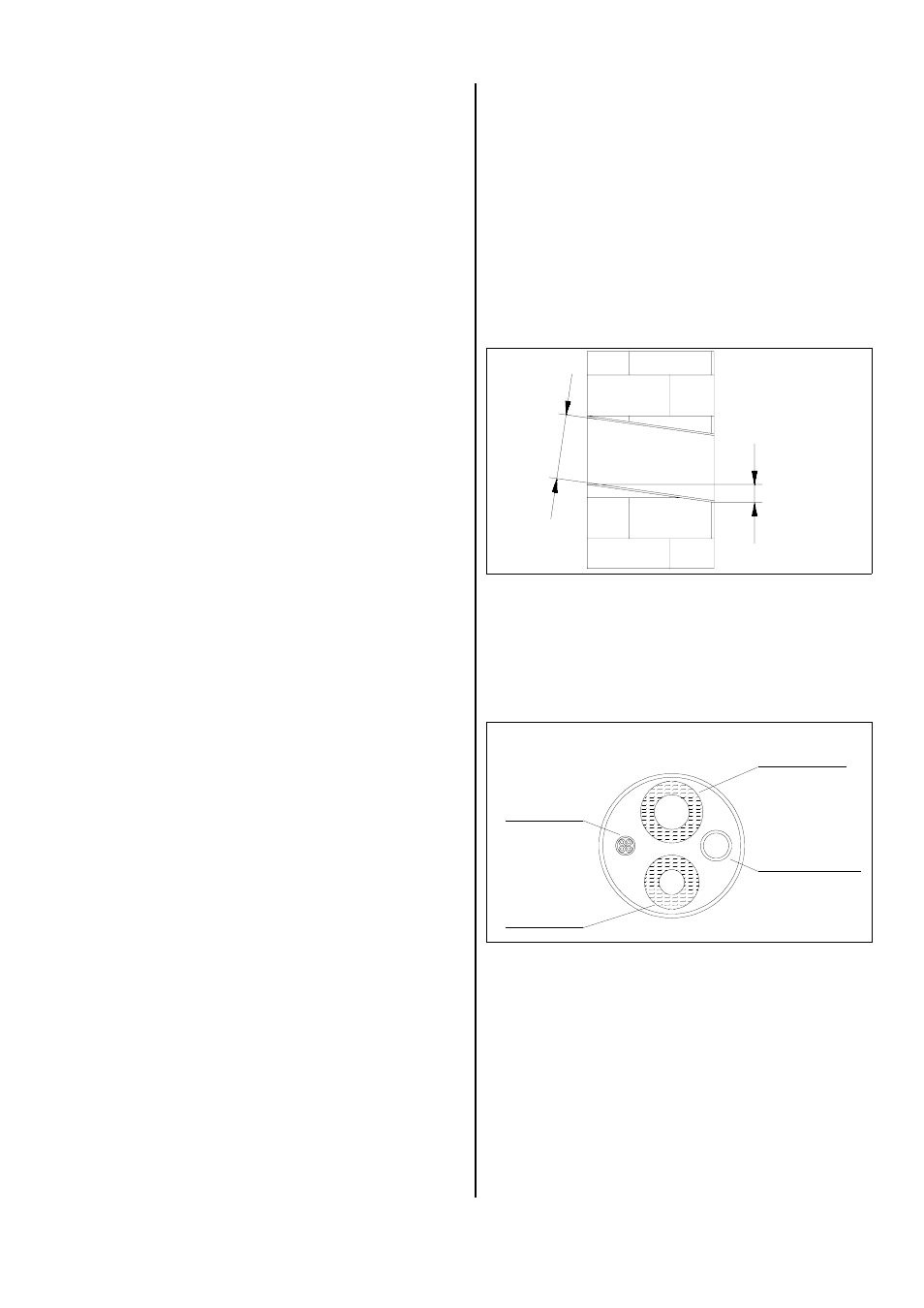
à For the connection lines to the outdoor part, a hole at
least 70 mm in diameter must be created.
à The hole must be placed at an incline of at least 10
mm or 2% from the inside to the outside.
Refrigerant
outlet line
Control line
Condensation
line
Refrigerant
intake line
à Before beginning work, make sure that there are no
supply lines (water, etc.) located in the vicinity of the
wall lead-through.
à We recommend cushioning the inside of the hole or
lining it with a PVC pipe to prevent the lines from be-
ing damaged.
à After assembly is complete, the wall lead-through
must be sealed with a suitable sealing compound.
Do not use any materials containing cement or lime!
min. 10 mm
min
.
70 mm
Outside
Inside
Wall lead-through diagram