Wiring diagram, Klm c 1~ m kl, Tb hw – REMKO ELT 18-S User Manual
Page 10
Advertising
10
L1 L2
L3
1 2 3 4 5
N
M1 C1 C2
6 7 8
KLM
C
1~
M
KL
2
1
3
4
5
6
13
14
1
2
C
2
1
3
4
5
6
13
14
2
3
K2
K1
NK
STB
L1 L2 L3 N PE
RT
A2
A1
S
A2
A1
TB
HW
V1
V4
L3
L1
V6
V3
M
H
V5
L2
V2
08/2004
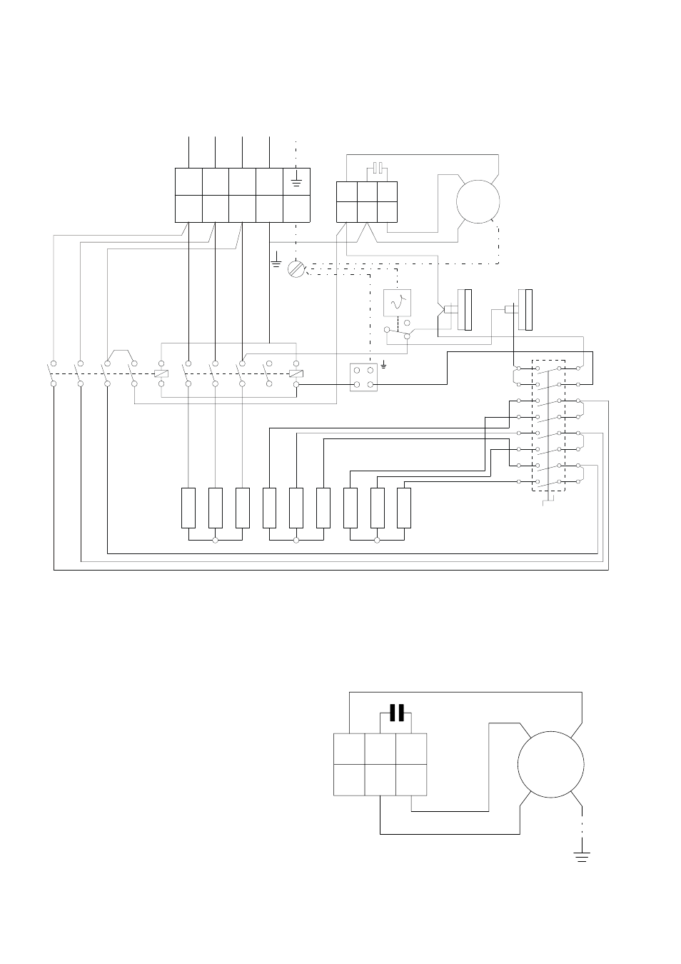
Wiring Diagram
KL = terminal strip
C = capacitor
KLM = terminal strip fanmotor
M = fanmotor
STB = temperature limiter (with sensor)
NK = recool thermostat
TB = temperature limiter
K1 = contactor 1
K2 = contactor 2
RT = thermostat socket
S = operating switch
HW = heating element
Wiring diagramm fanmotor
M1 C1
C2
6
7
8
blau
braun
schwarz
KLM
C
M
1~
3 N ~ 50 Hz 400/230
Advertising
This manual is related to the following products: