Wiring diagram – REMKO PGT 30 User Manual
Page 10
10
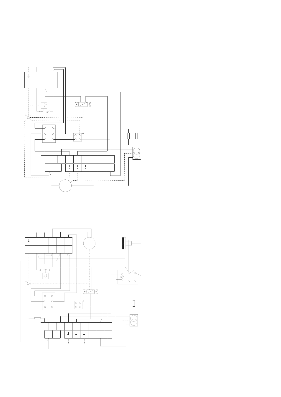
Wiring Diagram
PGT 100 / 100 E
STB
4
3
230 / 1~ 50Hz
PE
A3
A2
A1
B6
B4
B5
3
1
2
RT
S
8
A
RS
Z
I
ZT
KL
MV
pgt_30_60.prt M10
M
N
L1
N
L1
3
5
6
4
3
5
6
1 2
9
7
8
8
8
B
1~
HS = Auxiliary relay
I = Ionisation electrode
KL = Terminal strip
M = Fan motor
MV = Solenoid valve
NK = Re-cooling thermostat
RS = Relay socket
RT = Room-thermostat plug socket
STB = Safety temperature limiter
S = Switch
Z = Ignition electrode
ZT = Ignition transformer
I = Ionisation electrode
KL = Terminal strip
M = Fan motor
MV = Solenoid valve
RS = Relay socket
RT = Room-thermostat plug socket
S = Switch
STB = Safety temperature limiter
Z = Ignition electrode
ZT = Ignition transformer
We reserve the right to make changes to dimensions and design in the interest of technical progress.
PGT 30 / 30 E und 60 / 60 E
A3
A2
B6
B4
B5
S
A
RS
1
PE
KL
3
1
2
RT
STB
ZT
230 / 1~ 50Hz
A1
I
NK
Z
~
M
1
A1
11 14
HS
MV
L1 N
L1 N
2
3
1
2
3
4
5
6
9
8
7
6
5
4
3
2
1
8
8
8
B
A2
31 34
pgt_100.prt M10