REMKO ATR-4 User Manual
Page 10
10
For the authorised electrical installation personnel!
•
Connection and service may only be performed by authorised electri-
cal personnel
!
•
Prior to performing any work on the unit, all power lines must be free
of electrical current and secured against switching on again
!
•
Connection is to be performed in accordance with the wiring diagram
on page 12.
•
The unit may only be connected to lines that are permanently attached
in closed, dry rooms
.
•
When installing the unit, make sure that the electrical lines, for exam-
ple, power supply and relay connection lines, cannot come into con-
tact with low-current supply lines, such as sensor lines (minimum dis-
tance 4 mm for basic isolated line conductors).
•
Make sure that there is adequate protection to prevent connection
conductors from becoming loose that meets the requirements of EN
60730 Part 1. This can be achieved, for example, by securing the lines
with cable bindings
.
•
Compliance with VDE 0100, EN 60730, Part 1, as well as all regula-
tions of the local EVU must be assured
.
•
If the unit does not function as expected, first check the power supply
and that the unit has been properly connected
.
•
To prevent problems, the external sensor lines may not be laid to-
gether with the other power conducting lines. A minimum distance of 4
mm must be maintained for basic isolated conductors
.
•
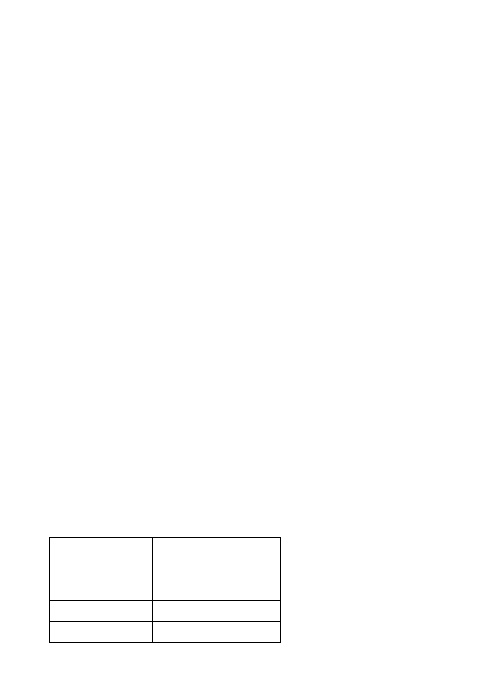
Use the sensor lines in accordance with the requirements. Observe
the maximum line length and required minimum cross-sections!
G
Warning:
The unit can be damaged if it is connected improperly! We
are not liable for damages that are the result of incorrect
connection and/or improper use
!
Installation Instructions
Max. line length
Line cross-section (Cu)
30 m
0.50 mm²
45 m
0.75 mm²
60 m
1.00 mm²
90 m
1.50 mm²