Block diagram, Technical data – REMKO PG 25 User Manual
Page 9
9
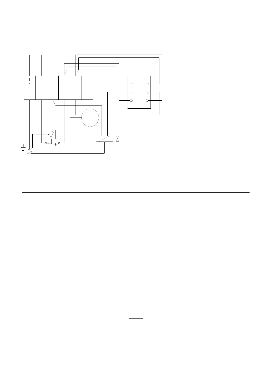
Block diagram
MV = Electric solenoid
M = Fan motor
STB = Safety thermostat
KL = Terminal strip
S = Operating switch
Note!
Any mode of operation other than specified in these operating instructions is not permissible!
Failing to observe it causes the customer to lose all rights to guarantee or damage claims.
A prerequisite for any material guarantee claims is that the orderer or the orderer’s customer filled
out a „guarantee certification” at the time of the purchase and start-up and returned it to
REMKO GmbH & Co KG. Guarantee certificates are enclosed with every REMKO-heater.
Technical data:
Series PG 25 PG 50
Nominal heat output kW 25 50
Heating capacity kW 10 – 25 25 – 50
Air output m³/h 800 1.450
Fuel/type of gas liquified gas Kat.
I
3 B/P
,
I
3+
Gas pressure bar 1,5 1,5
Gas consuption kg/h 0,78 – 1,95 1,95 – 3,95
Electrical connection 1~ V 230 230
Frequency Hz 50 50
Power consumption kW 0,07 0,11
Fuse-protection (required) A 10 10
Kind of protection IP 44 IP 44
Sound pressure level L
pA
1m
1)
dB(A) 56 – 69 62 – 72
Weight (without accessories) kg 12 20
Dimensions Length mm 450 650
Width mm 260 320
Hight mm 410 510
1) Noise measuring DIN 45635 - 01- KL 3
L1
N
1
2
3
5
4
1
2
3
6
KL
S
MV
STB
M
1~
230V/1~ 50Hz
PE
N
L1
A3
A2
A1
B6
B5
B4
We reserve the right to make modifications in dimensions and
construction in the interests of technical progress.