Description, Warranty – REMKO 4-Way Switching Valve User Manual
Page 5
5
Gas/oil boiler
Description
The four-way switching valve serves to
incorporate a boiler into systems (the
hydraulic diagram pictured below is an
example).
It is comprised of an electrical actuator
and a hydraulic lower section.
Due to its shape, the installed cylindrical
gate valve allows the medium to be re-
directed in a way which is not depend-
ent on the differential pressure.
This gate valve is controlled by an ac-
tuator.
The gate valve can also be operated
manually via a lever located on the plas-
tic housing.
This makes it possible to also operate
the four-way switching valve by hand,
without the electric motor.
The housing consists of corrosion-resist-
ant gunmetal (bronze).
The connections have a 5/4" inside
thread on both the inlet and outlet
sides.
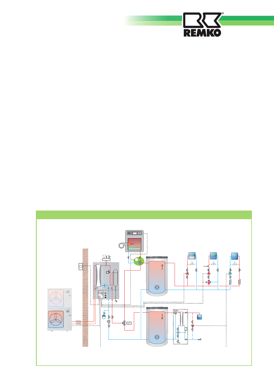
Hydraulic diagram as an example of the installation of a four-way switching valve
Outdoor unit
Indoor unit
CMF
Heating
circuit 1
Heating/cooling water
storage tank
KPS 300
Taps
CW inlet
Fresh water
station
Warranty
The warranty conditions are listed in the
"General terms and conditions".
Please contact your contractual partner
in the first instance.
Heating
circuit 2
Cooling circuit
Domestic water
storage tank
HPS 500
F9
F8
V
V
F17
F11
II
0
I
l/h
Tmax
F6
A
B
AB
M
A9
A8
A3
A6
A12
A8
A10
A1
M
F5
A2
A4/A5