Overview – RF Neulink NL900 User Manual
Page 5
11/16/2004
5
NL900 User’s Manual
1. Overview
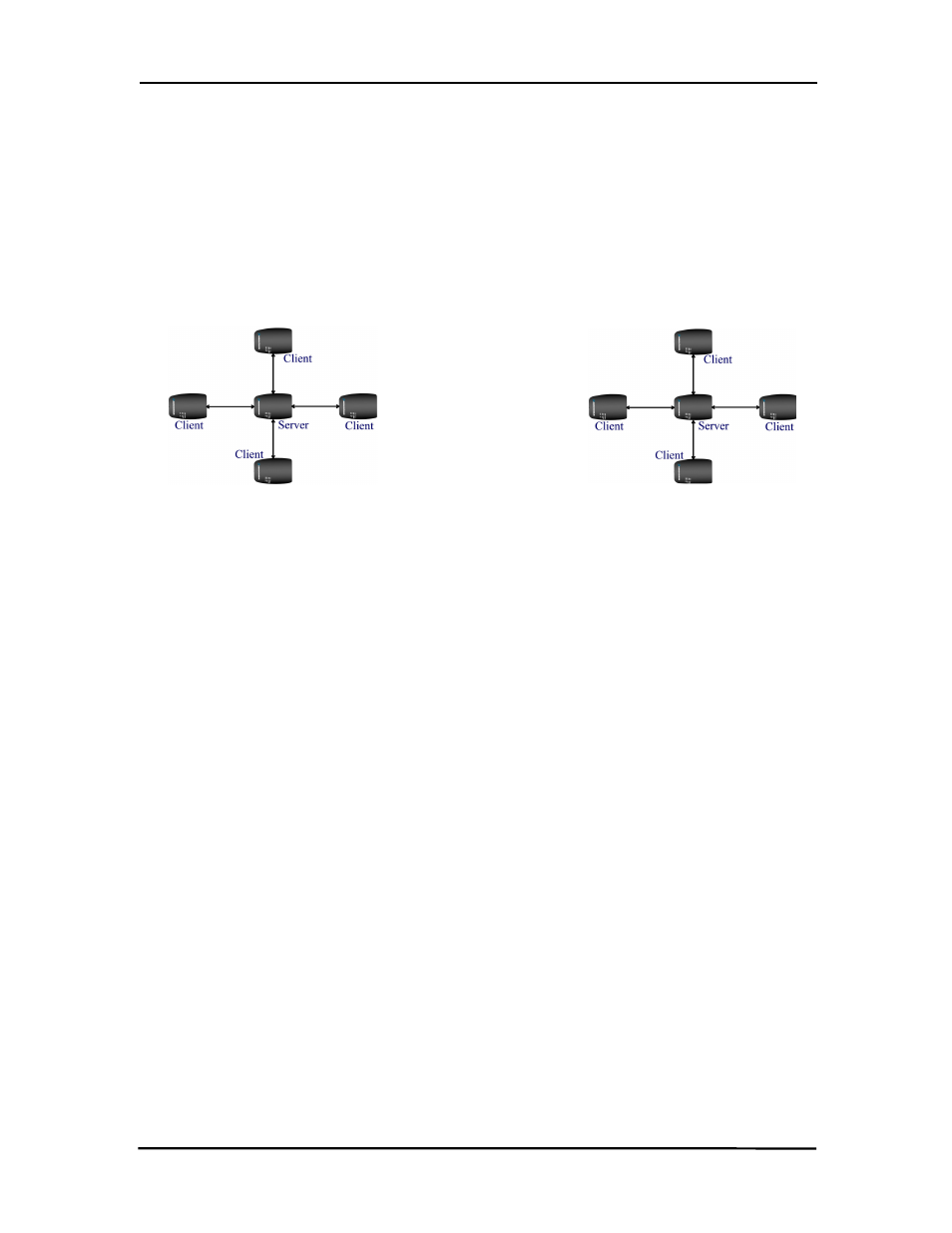
The NL900 product provides a wireless RS232 connection between different devices. Each
NL900 unit can be programmed as a Server or a Client, allowing for the creation of a two device
or multiple device wireless network. In addition, multiple networks can be created by
programming each network of NL900 units with a unique Channel Number and System ID
combinations. See Figure 1 below. To create a wireless network, simply program one of the
units as a Server and the other units as Clients.
Figure 1 - Multiple Networks Of NL900 Units
Example: Channel Number = 13
System ID = 123
Example: Channel Number = 25
System ID = 256
1.1
Flow Control
For optimal performance, Hardware Flow Control is strongly recommended. If the Clear To Send
(CTS) line is not used, there is a chance that the transmit buffer will fill up to its maximum limit
and data will be lost. W henever CTS is High, the NL900 is not ready to receive additional data
from its host. W hen CTS is Low, the NL900 is ready to receive data.
1.2
NL900 Definitions
1. PWR: Green LED indicates power is connected to the unit.
2. LINK: Red LED indicates the Client unit(s) and Server unit are in range of one another.
Link LED remains activated on Server units. Client units activate the Link LED when in
range of the Server unit
3. RX: Green LED indicates when a NL900 unit is receiving data.
4. TX: Red LED indicates when a NL900 unit is sending data.