Step 11 power port, Step 1-set output resolution, Step 2-input signal programming – RGBLink VSP 737 Quick Start User Manual
Page 2: Step 10-serial port power on, Local control-front panel operation, Step 9-usb port, Step 8 lan control port, Usb cable is used to connect vsp 737 and computer
VSP 737 Quick Start
Version 1.0
Page 2 of 3
ADD: S603 Weiye Building Torch Hi-Tech Industrial Development Zone, Xiamen, Fujian Province, P.R.C.
Fax:00865925771202
Email: [email protected] http://www.rgblink.cn
Step 11 Power Port
VSP 737 use dual power backups to connect IEC port
to the power input port of VSP 737, 85-265 volt AC is
available for VSP 737's power supply, and the present
worldwide power system is compatible for VSP 737.
Step 1-Set Output Resolution
Tap output button to open the resolution setup menu,
rotate the knob, select the required resolution and tap the
knob of NEXT button to confirm, system will log out in
seconds automatically.
10 output resolutions as below are feasible for
VSP 737: 800x600x60Hz, 1024×768×60Hz ,
1280×768×60Hz, 1280×1024×60Hz, 1366×768×60Hz,
1440x900x60_nrHz, 1440x900x60Hz, 1600x1200x60Hz,
1600x1200x60_rHz,1920x1080x60Hz;
NOTE
Step 2-Input Signal Programming
Termi
nal
Color of T568A
Color of T568B
1
Geen-White
Orange-White
2
Green
Orange
3
Orange-White
Green-White
4
Blue
Blue
5
Bule-White
Blue-White
6
Orange-White
Green
7
Brown-White
Brown-White
8
Brown
Brown
Definition of cross wire terminal
CAT5
crosswire
with
T568A
standard
for one end
and T568B
for the
other
T568A
T568B
Plug the cross
cable into RJ-
45 port
End Terminal
Step 10-Serial Port
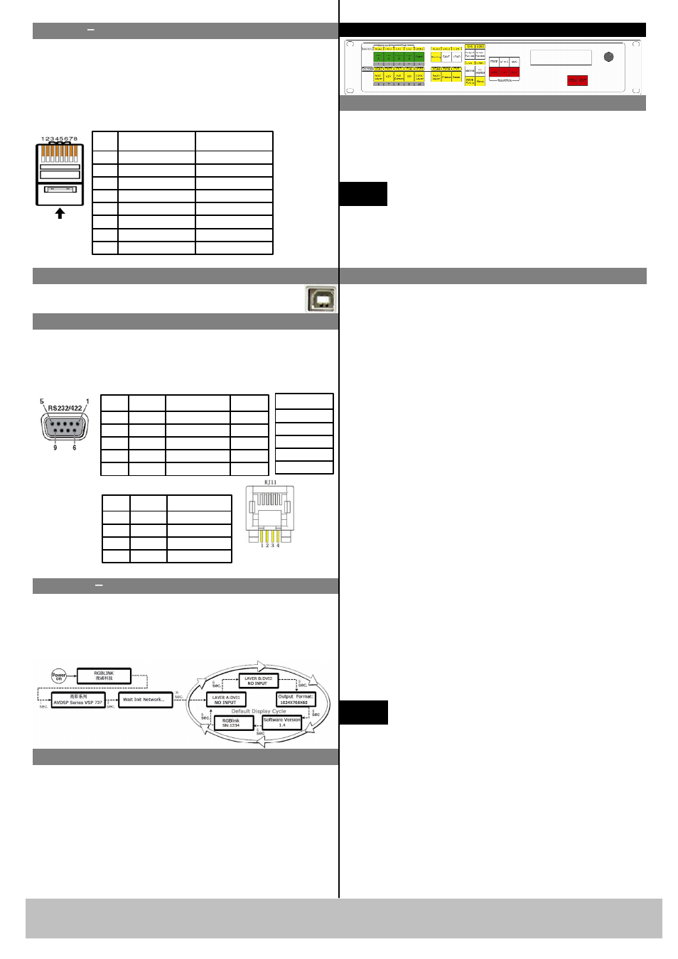
Power On
Turn on the mains switch, information about RGBlink
company and the device will be displayed on LCD
screen in turn. After self-test, device goes into the ready
mode, LCD screen will in turn show input signal and
format/ output format/ software version and device
serial number. User can control or adjust the device via
buttons on the front panel, TCP/IP, RS 232 or USB
remote operation.
For RS232-to-RJ11 cable, the RS232 end is used to
connect computer and other operating system, the RJ11
end is used to connect the RJ11 port on the rear panel
of VSP 737. Details are as below:
RS-232
Function
2
TX
Sending
3
RX
Receiving
5
GND
Ground Signalling
7
---
Without Use
8
---
Without Use
Termi
nal
RS-422
Function
TX-
Sending(-)
RX-
Receiving(-)
GND
Ground Signal
RX+
Receiving(+)
TX+
Sending(+)
Plug the
cross cable
into
RS232/RS422
port
Plug cross cable
into RJ11 port
RJ-11
Function
1
TX
Sending
2
RX
Receiving
3
GND
Ground Signal
4
---
Without Use
Termi
nal
Local Control-Front Panel Operation
VSP 737 has 8 composite video inputs, 4 VGA inputs
(compatible of YPBPR), 4 DVI inputs (compatible of
HDMI 1.3), 4 USB inputs, among these inputs, 4
composite inputs, 2 VGA inputs, 2 DVI inputs and 2
USB inputs are background input, corresponding to the
input signals from ports.
VSP 737 supports 4 channel input programming: Use
the PRO button and signal source composite button to
program on the input signal source, and preliminarily
monitor on the PREVIEW output port on back panel,
all programming is finished in the PREVIEW channel.
Programming steps are as below: Tap PRO button,
button light on, yellow background silkscreen
effective, present input signal sources of 4 channels
light on. The default input of LAYER A is: DVI1,
while LAYER B: DVI2, and BGA: DVI3, and BGB:
DVI4. Directly select the intended button to change for
other input signals, e.g. tag PRG button then CV2
button to change DVI1 signal to CV2 signal, the LCD
screen will show CV2 LAYER A. The same goes for
changing signals of other channels. After the setting,
tap PRG button, log out the programming function,
button light off, input signal programming finished.
NOTE
Step 9-USB Port
USB cable is used to connect VSP 737 and
computer.
Step 8
Lan Control Port
Apply the CAT5 crosswire, with T568A standard for
one end and T568B for the other. According to the
informational diagram below, users can apply the
RS232 or USB port to alter the default IP address
192.168.0.100 of device.
The corresponding input signal sources of
these 4 channels are as below:
LAYER A:CV1,CV2,VGA1,DVI1, USB1;
LAYER B:CV3,CV4,VGA2,DVI2, USB2;
BG A:CV5,CV6,VGA3,DVI3, USB3;
BG B:CV7,CV8,VGA4,DVI4, USB4;