RLE Wi-MGR Quick Start User Manual
Wi-mgr quick start guide
© Raymond & Lae Engineering, Inc. 2011. All rights reserved. RLE® is a registered trademark and Seahawk™, Falcon™, and Raptor™ are trademarks
of Raymond & Lae Engineering, Inc. The products sold by Raymond & Lae Engineering, Inc. are subject to the limited warranty, limited liability, and
other terms and conditions of sale set forth at http://rletech.com/RLE-Terms-and-Conditions.html.
Installation Supplies
Included with the Wi-MGR
Wi-MGR device
24VDC wall-mount power supply
CAT 6 Crossover Network Cable
Two antennae - 418MHz (longer shafts) & 900MHz (shorter shafts)
Rack-mount bracket
Available from RLE, sold separately
18 – 22 AWG ground wire
Wireless sensors and point repeaters, as necessary for your application
Optional supplies
18AWG shielded twisted pair stranded copper wire - no more than 2000ft (610m)
(Modbus RTU communication via EIA-485 port)
Straight-through CAT5 cable
Straight-through, nine-pin serial cable
Network Communications Information
Consult your IT administrator and determine the following Wi-MGR network
settings:
• IP Address _______________________________________________
• Subnet Mask _____________________________________________
• Default Gateway __________________________________________
Mount the Device
RLE recommends installing the Wi-MGR in a 19-inch rack and provides mounting
brackets with each Wi-MGR. Remove the screws from the side of the device, put
the brackets in place, and reapply the screws. Use the proper anchoring method to
mount the unit securely.
Provide a Power Supply and Ground Connections
Power the Wi-MGR from a UPS supply so the device can send alarm notifications
during a power outage. Power can be supplied to the Wi-MGR through either the
power jack and the provided wall adapter or the power supply terminal block.
1. Connect an 18AWG ground wire from the ground terminal (marked on the
upper left side of the enclosure) to a suitable earth ground.
2. Plug the provided wall adapter into the jack at P1 and the UPS outlet. The wall
adapter has a five foot (1.524m) power cord.
3. If you’re providing your own power supply, connect 24VDC to the unit through
the power terminal block.
Connect the Wi-MGR to the Network
The Wi-MGR needs network connectivity in order to access the web interface,
configuration screen, and to activate the email (SMTP), BACnet slave, Modbus slave,
and SNMP features. Use the provided CAT 6 crossover cable to the 10/100BASE-T
Ethernet port directly to a PC. Use a straight-through CAT 5 cable (purchased
separately) to connect the Wi-MGR to a network hub or switch.
EIA-232 Connection
The Wi-MGR can be connected directly to a PC through its EIA-232 port. Designed
for temporary use, this connection supports IP configuration, firmware downloads,
and troubleshooting. Connect via a straight through, 9-pin serial cable.
Connect the Antennae
The Wi-MGR is shipped with a 418MHz, 6-foot cable antenna and a 900MHz, 6-foot
cable antenna. The 418MHz antenna has longer shafts; the 900MHz antenna has
shorter shafts. Plug each antenna into its labelled jack on the front of the Wi-MGR.
Wi-MGR Quick Start Guide
Thank you for purchasing a Wi-MGR wireless sensor network manager. This guide outlines
basic Wi-MGR installation and configuration.
For additional installation and configuration instructions, download the Wi-MGR User Guide
from our website - www.rletech.com.
If you need further assistance, please email our support staff - [email protected] or call
us at 800.518.1519.
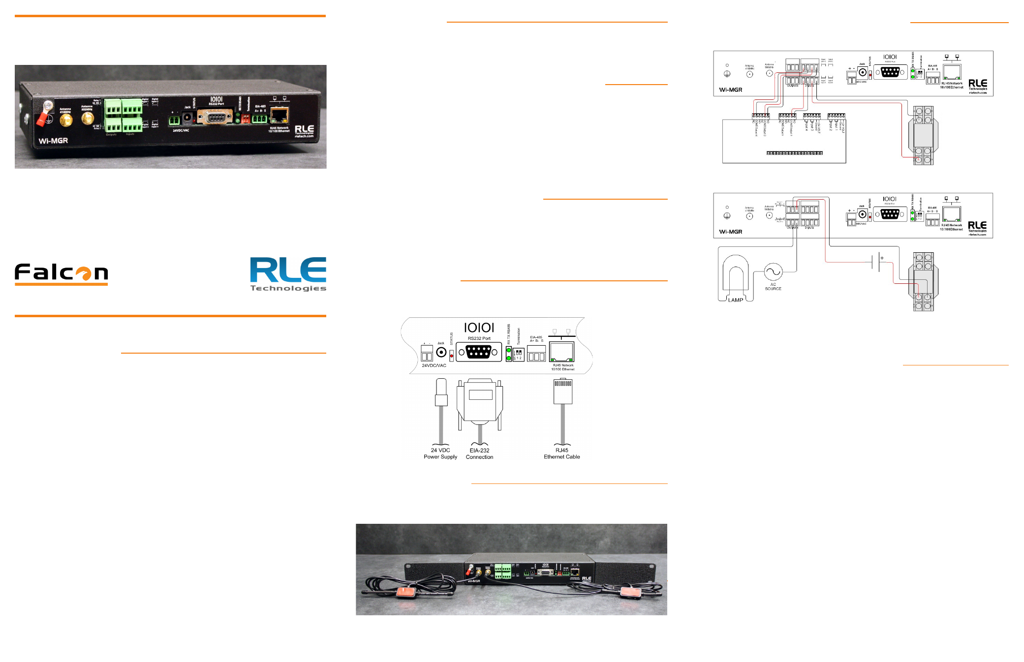
Wire the Relay Outputs and Digital Inputs
Four (4) wired digital inputs and two (2) wired relay outputs provide expanded
monitoring and notification capabilities. Your wired inputs may look like this:
Wired outputs may look like this:
Configure the digital inputs and relay outputs in the Configuration > Digital IO
section of the Wi-MGR web interface. Refer to the Wi-MGR User Guide for more
detailed information.
Set the IP Address Using a Web Browser
If you have not set an IP address before, consult your IT Department for support.
Note: The default IP address for the Wi-MGR is 10.0.0.188
The default Subnet Mask is 255.255.255.0
The default user name is fds (all lowercase)
There is no default password - leave the password field empty.
1. Contact your IT Department to obtain an available IP address, Subnet Mask,
and default Gateway.
2. Plug a crossover network cable (provided) into the laptop or workstation that
will be used to configure the Wi-MGR.
3. You’ll need to change the IP address and Subnet Mask of your computer so
it can communicate with the Wi-MGR in its factory-configured state. Before
you change anything, write down the original IP address and Subnet Mask of
your computer - you’ll need to revert back to these original settings once the
Wi-MGR is configured.
4. Change the IP address and Subnet Mask of the computer from its existing
address to one that will allow it to communicate with the Wi-MGR, such as
10.0.0.189. It may be beneficial to set the IP address to one that is one number
different from the Wi-MGR’s IP address (10.0.0.188).
5. Connect the other end of the crossover cable to the Ethernet port on the back
of the Wi-MGR.
6. Access the Wi-MGR through a Web browser — type the Wi-MGR’s IP address
(10.0.0.188) into the location bar. When prompted, enter the Wi-MGR user
name, which is fds. There is no default password, leave it blank.
7. Select the Configuration Menu link, then change the IP address, Subnet Mask,
and default Gateway to the one provided by your IT Department. Press the
Submit Changes button. The Wi-MGR will save the new IP address, Subnet
v1.1
(05/2013)