Installation & operations, Ba/#-(pp, rpp, rpfep) temperature sensor – RLE TSP User Manual
Page 3
Installation & Operations
Remote Probe Transmitters and Remote Sensor Transmitters
Building Automation Products, Inc., 750 North Royal Avenue, Gays Mills, WI 54631 USA
Tel:+1-608-735-4800 • Fax+1-608-735-4804 • E-mail:[email protected] • Web:www.bapihvac.com
Specifications subject to change without notice.
BA/#-(PP, RPP, RPFEP) Temperature Sensor
20921_ins_RemoteSen_Active
rev. 04/18/13
Wiring & Termination
BAPI recommends using twisted pair of at least 22AWG and sealant filled connectors for all wire connections. Larger gauge
wire may be required for long runs. All wiring must comply with the National Electric Code (NEC) and local codes. Do NOT
run this device’s wiring in the same conduit as high or low voltage AC power wiring. BAPI’s tests show that inaccurate signal
levels are possible when AC power wiring is present in the same conduit as the sensor wires.
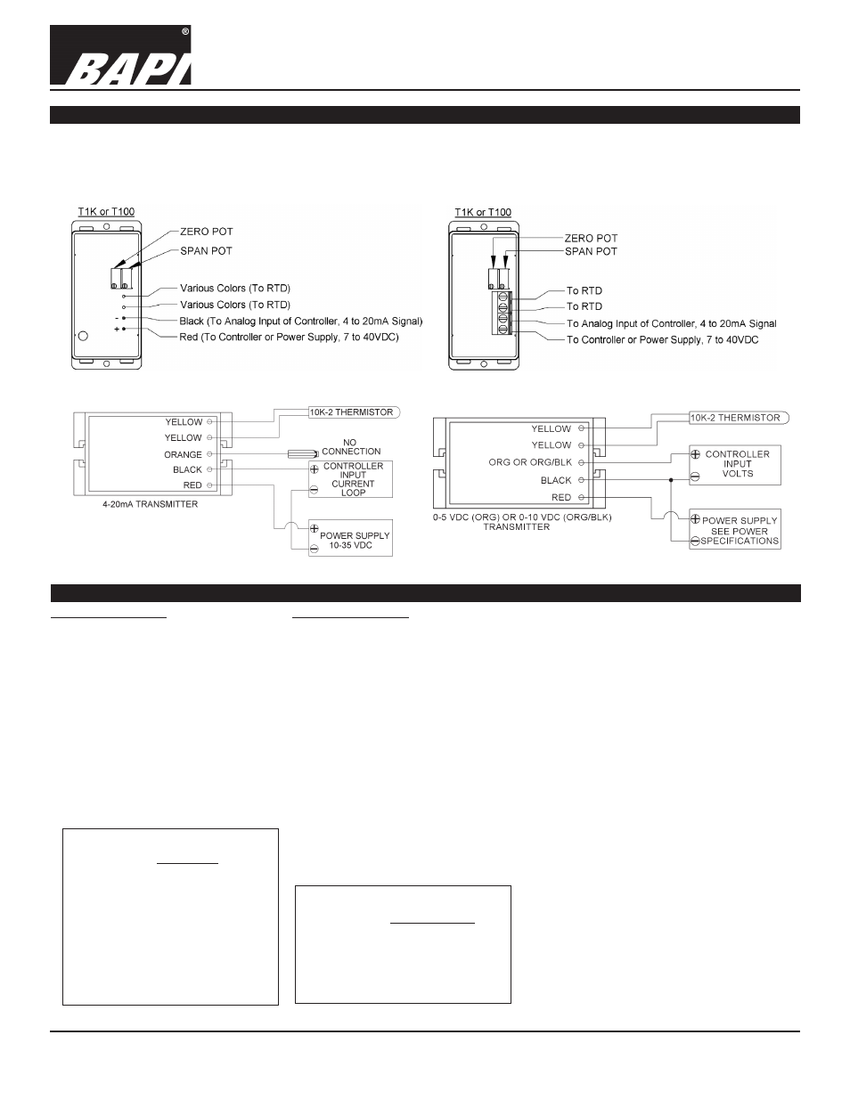
Fig. 16: Typical RTD 4-20 mA Transmitter W/Flying Leads
Fig. 18: Typical Thermistor 4 to 20mA Transmitter
Fig. 17: Typical RTD 4-20mA Transmitter W/Terminals
Fig. 19: Typical Thermistor Voltage Transmitter
Diagnostics
Voltage Temperature Equation
T = T
Low
+ (V x T
Span
)
V
Span
T
= Temperature at sensor
T
Low
= Low temperature of span
T
High
= High temperature of span
T
Span
= T
High
- T
Low
V
Low
= Low transmitter voltage
usually=(0, 1 or 2v)
V
High
= High transmitter voltage
usually=(5 or 10v)
V
Span
= V
High
- V
Low
V
= Signal reading in volts
4-20mA Temperature Equation
T = T
Low
+ (A -4) x (T
Span
)
16
T
= Temperature at sensor
T
Low
= Low temperature of span
T
High
= High temperature of span
T
Span
= T
High
- T
Low
A
= Signal reading in mA
Possible Problems:
Possible Solutions:
• Unit will not operate.
- Measure the power supply voltage by placing a voltmeter across the transmitter’s (+) and
(-) terminal. Make sure that it matches the drawings above and power requirements in the
specifications.
- Check if the RTD wires are physically open or shorted together and are terminated to the
transmitter.
- Measure the physical temperature at the temperature sensor’s location using an accurate
temperature standard. Disconnect the temperature sensor wires and measure the
temperature sensor’s resistance with an ohmmeter. Compare the temperature sensor’s
resistance to the appropriate temperature sensor table on the BAPI web site.
• The reading is incorrect in the controller. - Determine if the input is set up correctly in the controllers and BAS software.
- For a 4-20mA current transmitter measure the transmitter current by placing an ammeter
in series with the controller input. The current should read according to the “4-20mA
Temperature Equation” shown below.
- For a voltage transmitter, measure the signal with a volt meter (Orange or Orange/Black to
Black). The signal should read according to the “Voltage Temperature Equation” shown below.