RLE TH140D User Manual
Hwl series, Notice, Wall mount humidity sensor
VERIS INDUSTRIES
™
environmental SenSorS
inStallation GUiDe
Z202637-0Y
PAGE 1
©2010 Veris Industries USA 800.354.8556 or +1.503.598.4564 / [email protected]
09101
Alta Labs, Enercept, Enspector, Hawkeye, Trustat, Veris, and the Veris ‘V’ logo are trademarks or registered trademarks of Veris Industries, L.L.C. in the USA and/or other countries.
Wall Mount Humidity Sensor
Installer’s Specifications
HS Element
Digitally profiled thin-film capacitive (32 bit mathematics)
U.S. Patent 5,844,138
Accuracy at 25°C from 10-80% RH*
2%, 3%, or 5% models;
±1% at 12-60% RH in voltage output mode;
±1% at 12-60% RH in mA output mode with temp. transmitter;
±1% at 20-40% RH in mA output mode
(Multi-point calibration, NIST traceable)
Reset Rate**
24 hours
Stability
±1% @ 20°C (68°F) annually, for two years
Operating Humidity Range
0 to 100% RH (non-condensing)
Hysteresis
1.5% typical
Linearity
Included in Accuracy spec.
Temperature Coefficient
±0.1% RH/°C above or below 25°C (typical)
Analog Output
4-20mA version: 2-wire, polarity insensitive, (clipped and capped)
0-5V/0-10V versions: 3-wire, observe polarity
Scaling
0-100% RH
Operating Temperature Range
10° to 35°C (50° to 95°F)
Input Power***
4-20mA version: loop powered 12-30VDC only, 30mA max.
0-5V/0-10V versions: 12-30VDC/24VAC, 15mA max.
Optional Temperature Transmitter Output
Digital, 4-20mA, (clipped and capped) or
0-5V/0-10V output; accuracy ±0.5°C (±1°F) typical
EMC Conformance – CE Option
EN 50081-1, EN 50082-1, EN 61000-4-4, EN 61000-4-5, EN
61000-4-3, ENV 50204, EN 61000-4-6
*Specified accuracy with 24VDC supplied power with rising humidity. RTD/Thermistors are not
compensated for internal heating of product.
**Reset Rate is the time required to recover to 50% RH after exposure to 90% RH for 24 hours.
***One side of transformer secondary is connected to signal common, so an Isolation transformer
or dedicated power supply may be required.
Shielded cabling is required for conformance to EMC standards. Technical information is available
from factory upon request or is available on our website: www.veris.com
HWL SerieS
HWL SerieS
NOTICE
• This product is not intended for life or safety applications.
• Do not install this product in hazardous or classified locations.
• Read and understand the instructions before installing
this product.
• Turn off all power supplying equipment before working on it.
• The installer is responsible for conformance to all applicable codes.
Available
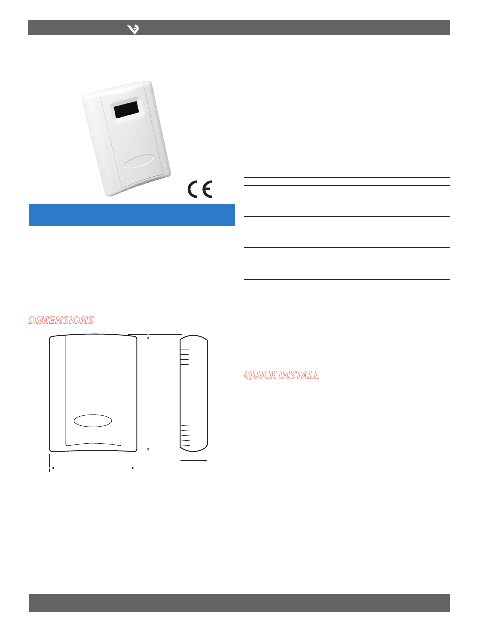
Dimensions
quick install
Select a mounting location away from ventilation sources. The sensor should be
1.
mounted on a vertical wall, about 4 1/2 feet above the floor.
Affix the backplate to the wall.
2.
Wire the device. Refer to wiring diagram.
3.
Install Cover.
4.
3.5"
(89 mm)
4.8"
(122 mm)
1.2"
(30 mm)