SL Power Electronics GPM40 User Manual
SL Power Electronics Equipment
6050 King St. Unit A
Ventura, CA 93003 + 805-486-4565
Internet: www.slpower.com
MODEL NUMBERS: GPM40A, GPM40B, GPM40D, and GPM40-X, where X represents the output
voltage, which may be any number from 3.3 through 28. Models may or may not be followed by suffix
–XXX and/or G, where XXX may be any number from 001 thru 999. The –XXX suffix are used for
value added configurations that have no impact on safety and suffix G indicates compliance to RoHS.
RATINGS:
Input: 100-240 V ac, 1.3 A, 50/60Hz
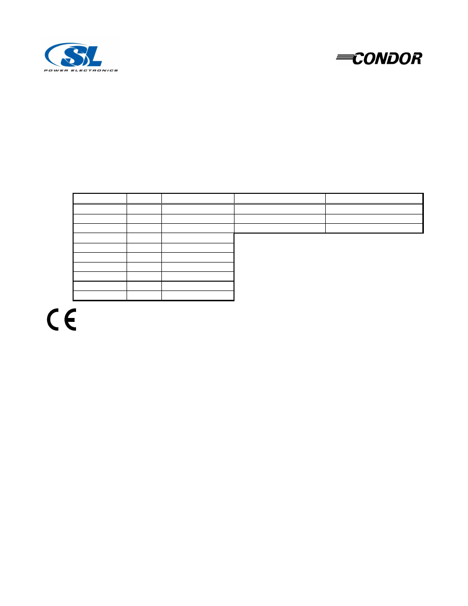
Outputs: 40 W max or see table for standard output voltage models.
Model
Watts
1
Output #1
Output #2
Output #3
GPM40A
40
+5.1 V dc 4 A
+12 V dc 2 A
-12 V dc 0.4 A
GPM40B
40
+5.1 V dc 4 A
+15 V dc 2 A
-15 V dc 0.4 A
GPM40D
40
+5.1 V dc 4 A
+24 V dc 1 A
-12 V dc 0.4 A
GPM40-3.3
26.4
3.3 V dc 8 A
Notes:
GPM40-5
40
5.0 V dc 8 A
1. Maximum continuous output power at 50 °C - Total
GPM40-9
40
9.0 V dc 4.4 A
of all Outputs.
GPM40-12
40
12.0 V dc 3.4 A
2. Maximum Relative Humidity 96 %, no condensation.
GPM40-15
40
15.0 V dc 2.7 A
3. Storage: -40 to +85 °C. Units should be allowed to
GPM40-24
40
24.0 V dc 1.7 A
warm-up under non-condensing conditions
GPM40-28
40
28.0 V dc 1.5 A
before application of power.
SAFETY DECLARATION: Condor DC Power Supplies, Inc. declares under our sole
responsibility that all models listed above are in conformity with the applicable requirements
of EN 60950-1 following the provisions of the Low Voltage Directive 73/23/EEC. All
models are Certified to be in compliance with the applicable requirements of UL 544, UL 2601-1, UL
60950-1, CSA 22.2 No. 601.1 (L3M1), and EN 60601-1.
CLASSIFICATION:
(5.1) Protection against electric shock = Class I
(In accordance with
sub- clause 5
(5.2) Degree of protection against electric shock = Not acceptable for applied
part without additional isolation (contact factory for details)
of EN 60601-1)
(5.3) Protection against harmful ingress of water = Ordinary (no protection)
(5.5) Have not been evaluated for use in the presence of a flammable anaesthetic
mixture with air, oxygen, or nitrous oxide. This evaluation is to be made on the
end equipment by the OEM.
(5.6) Mode of operation = Continuous
GROUNDING: The Protective Earth (ground) terminal must be bonded to Protective Earth in the host
equipment. Using the Protective Earth terminal on the supply for grounding the host equipment is not
recommended. A separate dedicated grounding point should be used.
OUTPUTS: All output commons should be connected to Protective Earth in the end application. The
output(s) are intended for Protectively Earthed Signal Output and Intermediate Circuits only. The
output(s) are not acceptable for patient connection without additional isolation. All DC outputs are
SELV under normal and single fault conditions.
41-32580-0001 Rev. J 6/5/06
Page 1 of 2