SL Power Electronics GPM80 User Manual
Gpm80 series installation instructions
41-32414-0001 Rev. E 11/13/06
SL POWER ELECTRONICS CORP.
6050 King Drive, Bldg. A
Ventura, CA 93003 + 805-486-4565
Internet: www.slpower.com
MODEL NUMBERS: GPM80X where X may be the letter A, B, C, D, E or P, and GPM80-X where X may be
the number 5, 12, 15, 24, or 28. Models may be followed by -PF, -L, -LC, -FB, -TB, -XXX and/or G. Suffix -PF
indicates Power Failure, -L indicates L bracket, -LC indicates L bracket and cover, -FB indicates flux band, -TB
indicates terminal block, -XXX indicates value added configurations that have no impact on safety which may be
any number from 001 thru 999, and/or G indicates compliance to RoHS.
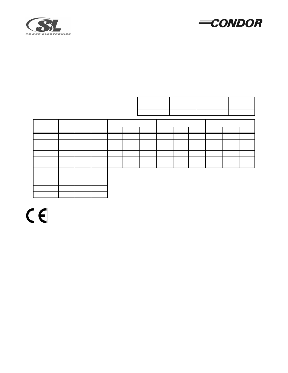
RATINGS:
Input: 100-240 V ac, 3.2 A, 50/60 Hz
Output: Maximum Continuous Power, total of all
outputs at ambient of 50 °C.
Without Cover
26 CFM
With Cover
26 CFM
Without Cover
0 CFM
With Cover
0 CFM
110 Watts
90 Watts
80 Watts
40 Watts
Output #1 (Note 3)
Output #2 (Note 3)
Output #3
Output #4
MODEL
Note 1
Note 2
Note 1
Note 2
Note 1
Note 2
Note 1
Note 2
GPM80A
+5 V
12 A
12 A
+12 V
3.0 A
4.0 A
-12 V
1.0 A
1.2 A
+12 V
1.0 A
1.2 A
GPM80B
+5 V
12 A
12 A
+12 V
3.0 A
4.0 A
-12 V
1.0 A
1.2 A
-5 V
1.0 A
1.2 A
GPM80C
+5 V
12 A
12 A
+12 V
3.0 A
4.0 A
-15 V
1.0 A
1.2 A
+15 V
1.0 A
1.2 A
GPM80D
+5 V
12 A
12 A
+24 V
2.0 A
3.0 A
-12 V
1.0 A
1.2 A
+12 V
1.0 A
1.2 A
GPM80E
+5 V
12 A
12 A
+24 V
2.0 A
3.0 A
-15 V
1.0 A
1.2 A
+15 V
1.0 A
1.2 A
GPM80P
+5 V
12 A
12 A
+24 V
3.5 A
4.5 A
-12 V
1.0 A
1.2 A
+12 V
2.0 A
2.0 A
GPM80-5
+5 V
16 A
20 A Notes: 1. Maximum ratings for 0 CFM airflow.
GPM80-12 +12 V 6.7 A
9.2 A
2. Maximum ratings for 26 CFM airflow.
GPM80-15 +15 V 5.3 A
7.3 A
3. Sum of outputs #1 & #2 not to exceed 14A with 0 CFM airflow.
GPM80-24 +24 V 3.4 A
4.6 A
4. Maximum Operating Relative Humidity 96%, no condensation.
GPM80-28 +28 V 2.9 A
3.9 A
5. Storage: -40 to +85 °C. Units should be allowed to warm-up
under non-condensing conditions before application of power.
SAFETY DECLARATION:
SL Power Electronics Corp. declares under our sole responsibility
that all models listed above are in conformity with the applicable requirements of EN60950-1
following the provisions of the Low Voltage Directive 73/23/EEC. All models are Certified to be in
compliance with the applicable requirements of UL 60601-1, CSA 22.2 No. 601.1 (L3M1), and EN 60601-1.
CLASSIFICATION:
(5.1) Protection against electric shock = Class I
(In accordance with sub-
(5.2) Degree of protection against electric shock = Signal output or intermediate
clause 5 of EN 60601-1)
(5.3) Protection against harmful ingress of water = Ordinary (no protection)
(5.5) Not suitable for use in the presence of flammable anesthetic mixture.
This evaluation is to be made on the end equipment by the OEM.
(5.6) Mode of operation = Continuous
GROUNDING: The Earth (ground) terminal J1, pin 1 and all of the pads around the mounting holes must be
bonded to Protective Earth in the host equipment. Metallic spacers should be used to mount supply to metal
surfaces. When mounting to non-metallic surfaces, connect all mounting pads together and bond to earth. Using
the Earth terminal on the supply for grounding the host equipment is not recommended. A separate dedicated
grounding point should be used.
OUTPUTS: The output(s) are not acceptable for direct patient connection without additional isolation. All DC
outputs are SELV under normal and single fault conditions and are not an energy hazard.
GPM80 SERIES
INSTALLATION INSTRUCTIONS