Sloan 601 Prison Flushometer User Manual
Page 5
5
A
Secure flanged end of F-100 flush connection to the 1-1/2”
(38 mm) pipe using a 1-1/2” F-2-A coupling nut with S-21 gasket.
Tighten securely.
For urinals using a Model 613 or 9613 Valve, secure flanged
end of F-15-A flush connection to the 3/4” (19 mm) pipe using a
3/4” F-2-AW slip joint coupling (rubber gasket, nylon slip gasket and
coupling nut). Tighten securely.
Attach Plastic Tubing to Push Button Actuator. See: Steps to Attach
Plastic Tubing below.
A
The push button valve actuator is connected to the flushometer body
by two plastic tubes, marked “L” and “O”. Match markings on the
tubes to markings on the actuator
A
C
Slide spring over metal push button until it snaps into place.
Insert metal push button into button flange.
C
Slide plastic tubing into its corresponding valve actuator fitting. Pull
tubing to make sure connection is secure. (Tubing can be removed by
pressing on blue connection button to release.)
D
From front of panel, insert button flange assembly into hole of panel.
Behind panel, place washer over threads of button flange. Thread
button flange onto actuator. Tighten flange securely.
BUTTON FLANGE
METAL PUSH BUTTON
SPRING
PANEL
WASHER
ACTUATOR
ASSEMBLY NUT
PUSH BUTTON
ACTUATOR
QUICK
CONNECT
FITTINGS (2)
PLASTIC
TUBING
DUE TO THE HIGH BACK PRESSURES THAT CAN BE CREATED
BY STAINLESS WATER CLOSETS AND COMBINATION FIXTURES,
THE FOLLOWING PROCEDURES MUST BE FOLLOWED WHEN
INSTALLING THE FLUSH CONNECTION. FAILURE TO FOLLOW
THESE PROCEDURES CAN RESULT IN SEPARATIONS.
FOR SECURE CONNECTIONS IN HIGHER PRESSURE AND OTHER
SEVERE CONDITION APPLICATIONS, THE FLUSH CONNECTIONS
CAN BE SWEAT SOLDERED. REMOVE ALL PLASTIC AND RUBBER
GASKETS BEFORE BEGINNING SOLDERING PROCESS.
!!! IMPORTANT !!!
WHEN CUTTING SCORED TUBES TO FIT, ALWAYS KEEP
AT LEAST 1-1/4” (32 MM) OF SCORING TO ASSURE PROPER
ENGAGEMENT WITH COMPRESSION COUPLING.
!!! IMPORTANT !!!
MUST USE SLOAN APPROVED TUBING ONLY
!!! IMPORTANT !!!
Sloan Prison Flushometers are designed to connect to a
stainless steel prison fixture in the chase behind the wall.
A 1-1/2” (38 mm) pipe connection (NOT supplied by Sloan)
must be used to connect the fixture inlet from the wall to the flush
connection. For urinals using a Model 613 or 9613 valve,
a 3/4” (19 mm) pipe connection must be used to connect the
fixture inlet from the wall to the flush connection.
NOTE
FIXTURE SIDE
OF WALL
1-1/2”OR 3/4”
I.P.S. PIPE
CONNECTION
(NOT SUPPLIED
BY SLOAN)
S-21 GASKET
F-2-A
COUPLING NUT
F-100 FLUSH CONNECTION*
(SUPPLIED 3-1/4” LONG)
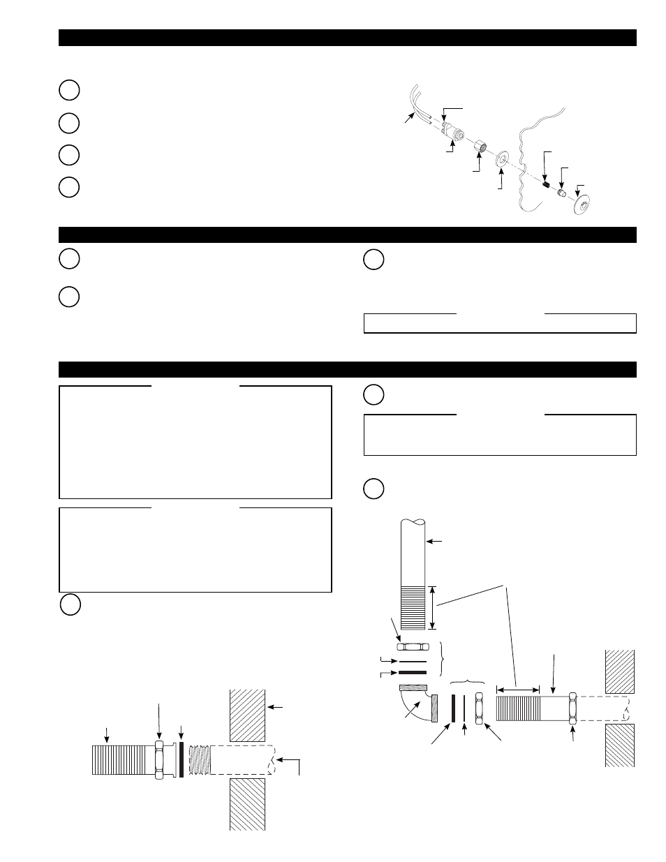
B
Cut Vacuum Breaker and Flush Connection tubes to length.
F-2-A
COUPLING NUT
F-100 FLUSH
CONNECTION
SLIP JOINT
COUPLING
VACUUM
BREAKER
ELBOW
RUBBER
GASKET
RUBBER
GASKET
NYLON
SLIP
GASKET
COUPLING
NUT
NYLON
SLIP
GASKET
COUPLING
NUT
IMPORTANT: WHEN CUTTING SCORED
TUBES TO FIT, ALWAYS KEEP AT
LEAST 1-1/4” (32 mm) OF SCORING TO
ASSURE PROPER ENGAGEMENT WITH
COMPRESSION COUPLING.
MBPM (METAL BUTTON - PANEL MOUNT) VARIATION HY-108-A METAL PUSH BUTTON ACTUATOR
Note: Use HY-108-A metal push button actuator on punched stainless steel plates and security fixtures with front access.
B
Thread actuator assembly nut onto threaded end of push button
actuator.
B
Cut off excess plastic tubing with plastic tube cutter (PTC) so that
there will be about 3” to 4” (76-102 mm) of slack when push button
actuator is installed. If the “L” and “O” markings on the tube will be
cut off, remark the tubing appropriately to not lose identification.
C
Slide the coupling nut, nylon slip gasket and rubber gasket onto the
vacuum breaker and flush connection tubes.
2B - INSTALL PUSH BUTTON ACTUATOR – HYDRAULIC PUSH BUTTON APPLICATION ONLY
STEPS TO ATTACH PLASTIC TUBING
3 - INSTALL VACUUM BREAKER AND FLUSH CONNECTION