Parts list, Operation – Sloan EW-72000 Installaton User Manual
Page 11
The information contained in this document is subject to change without notice.
When assistance is required, please contact Sloan Valve Company Installation Engineering Department at:
1-888-SLOAN-14 (1-888-756-2614)
OR
1-847-233-2016
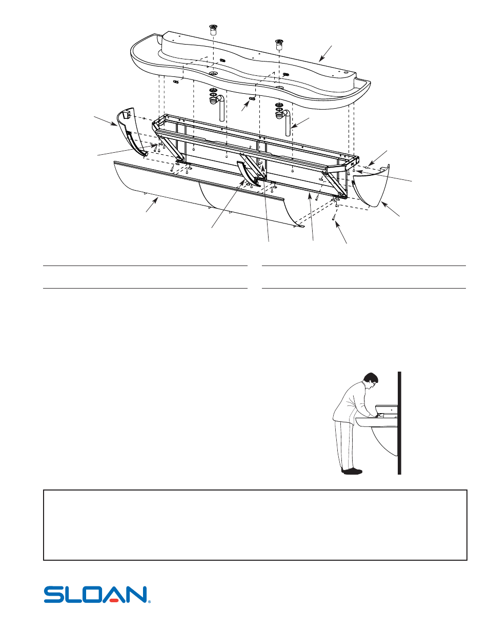
11
13
6
4
9
2
3
1
7
5
12
8
Parts List
Item Part
Description
No. No.
1
EW-30-A
Cabinet Weldment, 3 Station
2
EW-50
Front Panel Support - Machined
3
EW-36
Screw, Pan Head #8-32 x 7/16” Long (SEMS) (2)
4
EW-99
U-type Nut, Standard 1/4-20 Thread (8)
5
EW-60
End Cap Right - Machined
6
EW-52
End Cap Left - Machined
7
EW-16
Screw, Pan Head 1/4-20 x 1” Long (SEMS) (4)
Item Part
Description
No. No.
8
EW-15
Screw, Pan Head 1/4-20 x 1/2” Long (SEMS) (2)
9
EW-35
Front Panel, 3 Station (2)
10
EW-54
Triple Station Lavatory Basin Assembly
11
ETF-725-A
Grid Strainer Assembly (2)
12
EW-15
Screw, Pan Head 1/4-20 x 1/2” Long (SEMS) (8)
13
EW-61
Overflow Cover Plate (2)
—
EW-98
Light Duty Buffing Pad (Not Shown)
Operation
As the user’s hands pass under the spray head and enter the beam’s effective
range, the beam is reflected back into the sensor receiver and activates the
solenoid valve allowing water to flow from the Spray Head. Water will flow until
the user’s hands are removed from under the Spray Head or until the automatic
time out limit setting is reached.
SLOAN VALVE COMPANY • 10500 Seymour Avenue • Franklin Park, IL 60131
Phone: 1-800-9-VALVE-9 or 1-847-671-4300 • Fax: 1-800-447-8329 or 1-847-671-4380
www.sloanvalve.com
Printed in the U.S.A. 03-07
Copyright © 2007 SLOAN VALVE COMPANY
EW-73000 Triple Station Cabinet and Basin Assemblies
10