Operation – Smithco Big Vac V72E Operator Manual (2010) User Manual
Page 11
9
Service
OPERATION
Before operating this machine, become familiar with all controls and functions of this unit and the tow vehicle.
Also complete all maintenance requirements and read all safety warnings. By knowing both machines thor-
oughly, how it operates and by doing the prescribed maintenance steps, you can expect relatively trouble-free
operation for years to come.
TOW VEHICLE
You will need a 40 HP minimum tow vehicle.
1. Clevis Hitch - You will need a
3
/
4
diameter by 4" pin with some type of lock.
2. 3-Point Ball Hitch - You will need a 2" ball and a locking pin for the coupler.
DAILY CHECKLIST
1. Check engine oil level in tow vehicle. Add as needed. DO NOT OVERFILL.
2. Tire pressure should be 18 psi (1.3 bar) on Big Vac tires and 20 psi (1.4 bar) on castor wheels.
3. Check hardware for loose or missing nuts, bolts, screws, etc., and tighten or replace as needed.
4. Inspect hydraulic lines for damage or leaks. Never use hands to inspect leaks.
5. Check hydraulic fluid level in tank. Look at the sight gauge on the front left side of the tank. The oil level
should be at 90°C (194°F). If level is low, add SAE 10W-40 API Service SJ or higher motor oil.
6. Check controls for smooth, proper working operation. Lubricate as needed.
7. Check and clean all debris from blower housing.
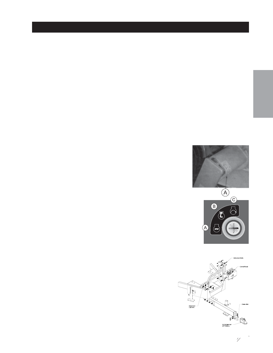
ADJUSTMENT OF BELT TENSIONER
There are four maximum belt tensioners on the Big Vac. Two control the tension
on the belts on the blower housing, one each on the finger reel and the thatcher
reel. The proper tension of the idler should be 12 to 15 as per the gauge (A) on
the side of the tightener. Over tightening the belt will shorten the life of the belt
and the machine may not perform to the best of its ability. To adjust belt
tensioner, loosen bolt holding tensioner. Bring idler pulley tight to belts and turn
tensioner into belts to 15°. Tighten holder bolt.
STARTING ENGINE
1. Make sure the fuel flow valve, located on the fuel tank, is “ON.”
2. The ignition switch is located on remote operator control panel. Insert key (A)
and turn clockwise until engine starts (C). Release key and it will return to run
position (B). Use choke and hand throttle as necessary.
3. Allow engine to idle and warm up a few minutes.
4. Be sure the jack is all the way up and will clear all ground ob-
stacles.
CONTROL PANEL ADJUSTMENT ARM
On the right hand side of machine is the adjustment lock arm, by lifting
up you can adjust the control panel by moving it forward or rearward.
Make certain that the lock arm is locked back in place after adjustment.
For up and down adjustment loosen the four adjustment bolts place the
control panel to where you want it and tighten the four bolts.