SOMFY DECOFLEX WIREFREE RTS User Manual
Decoflex wirefree rts switch
STOP
STOP
Thin side over outer edge of box
3. Place the flat side of mounting
bracket (included) against the wall
and align the thin side over the
outside edge of the existing
electrical box (opposite the stud
side). Center the bracket to align
the mounting screw height with
existing switch, then trace the
inside shape of the bracket on wall
using a pencil or thin marker.
4. Using a dry-wall saw (or
similar) begin to cut the dry-
wall along the traced outline.
Do not cut hole larger than
outline as this may result in
a loose fitting bracket. *For
greater accuracy please
refer to the recommended
hole dimensions on reverse
page.
The DecoFlex RTS Switch is a wireless radio transmitter compatible with all Somfy RTS Motors and
externally mounted RTS receivers.
TM
The Somfy DecoFlex WireFree RTS switch is a low voltage device which in many cases does not require
an electrical box. It can be mounted adjacent to an existing Decora style light switch or as a stand-alone
device using the (included) SOMFY low voltage mounting bracket (See installation section for details).
2
1
-
- Power: 3V lithium battery, CR 2450 type
o
o
o
o
- Operating temperature: +5 C/41 F to +40 C/104 F
- Range: Up to 65 Ft.
- Fits into standard Decora Wall Plates
Commands are transmitted by radio waves at 433.42 MHz.
Programming/Operating/Assembly Installation Instructions
TM
DecoFlex WireFree RTS Switch
DESCRIPTION
PROGRAMMING
1 CHANNEL
White: 1810897
Ivory: 1810898
Black: 1810899
TM
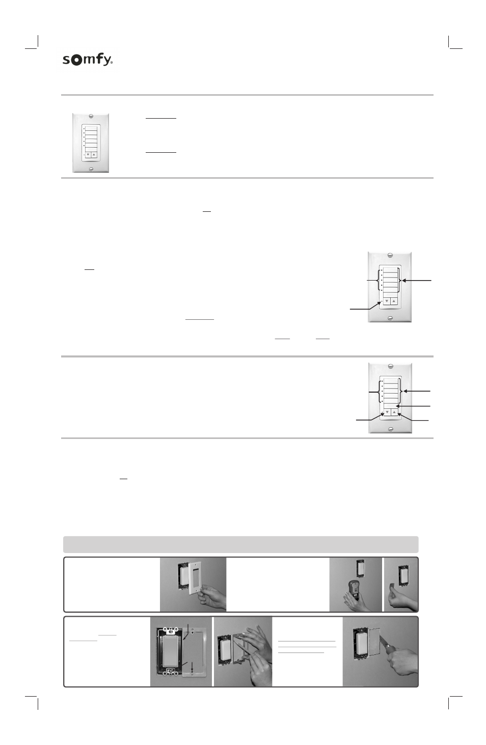
A. ADDING A DECOFLEX WIREFREE RTS WALL SWITCH - INITIAL INSTALLATION
NOTE:
During initial programming it is recommended to provide power only to the motor or RTS receiver being programmed.
1. Set the RTS Receiver or Motor into Programming Mode (Refer to the installation instructions of the relevant RTS receiver or motor for this procedure).
2. Select a Channel to be memorized by pressing the appropriate CHANNEL BUTTON. The adjacent LED will light to indicate the channel has been selected. (See figure 1)
TM
3. Using a paperclip or similar device, briefly press the programming button (1 second max) located on the DecoFlex WireFree switch (See figure 1). The RTS receiver or motor will
confirm the addition of the new DecoFlex switch in their respective manners.
FIGURE 1
TM
C. DELETING SPECIFIC CHANNELS OR DECOFLEX WIREFREE WALL SWITCH FROM MEMORY
1. Using a paperclip or similar device, press and hold the program button (for 3 seconds) on a previously addressed DecoFlex
switch or channel in memory (See figure 1). NOTE: This SHOULD NOT be performed with the device or channel intended for deletion.
The RTS receiver or motor will confirm programming mode in their respective manners.
2. Select a Channel to be deleted by pressing the appropriate CHANNEL BUTTON. The adjacent LED will illuminate to indicate the channel has been selected (See figure 1).
NOTE:
Only one channel can be deleted per procedure.
To remove/delete additional channels, proceed to Step 3 then start at Step 1 for each channel to be deleted.
3. Using a paperclip or similar device, briefly press the programming button (1 second max) located on the DecoFlex switch (See figure 1). The RTS receiver or motor will
confirm the deletion of the selected channel or DecoFlex switch in their respective manners.
TM
B. ADDING ADDITIONAL CHANNELS OR DECOFLEX WIREFREE WALL SWITCHES
1. Using a paperclip or similar device, press and hold the program button (for 3 seconds) on the previously addressed DecoFlex
switch or channel in memory. The RTS receiver or motor will confirm programming mode in their respective manners.
2. Select a NEW channel or DecoFlex switch to be memorized by pressing the appropriate CHANNEL BUTTON.
The adjacent LED will illuminate to indicate the channel has been selected (See figure 1).
3. Using a paperclip or similar device, briefly press the programming button (1 second max) located on the DecoFlex
switch (See figure 1). The RTS receiver or motor will confirm the addition of the new channel or DecoFlex switch
in their respective manners.
Program
Button
Select the
Channel
Button(s)
3
TM
OPERATING THE DECOFLEX WIREFREE WALL SWITCH
1. Select the CHANNEL BUTTON(s) programmed to a specific window covering(s). The adjacent LEDs will illuminate
to indicate the channel(s) selected (press CHANNEL BUTTON(s) in successive order to DESELECT,the adjacent LEDs
will extinguish to indicate the deselected channels).
2. To raise the window covering(s), press the UP button. To lower the window covering(s), press the DOWN button.
3. To stop the window covering(s) at any time, simply press the STOP button (see figure 2).
4. If a “Preferred Position” has been programmed, the window covering(s) can be commanded to travel to a preprogrammed
intermediate position.(Refer to the installation instructions of the relevant RTS receiver or motor for this procedure).
Select the
Channel
Button(s)
STOP
Button
UP
Button
DOWN
Button
FIGURE 2
LED
Indicator
LED
Indicator
5 CHANNEL
White: 1810813
Ivory: 1810814
Black: 1810830
INSTALLATION
4
Included is a special SOMFY low voltage device mounting bracket which attaches to drywall and eliminates the need for an electrical box.
The bracket can be used in two mounting type configurations, they are as follows:
TM
1. The bracket is specifically designed for mounting the DecoFlex WireFree RTS wall switch to an adjacent (pre-existing) Decora style light switch (see below).This
unique mounting bracket allows the necessary spacing for 2 adjacent switches and a new "Double Gang" (2 Gang) wall plate to be installed (See photo 8) resulting
2. The bracket can also be used for individual or "stand-alone" (1 switch) mounting configurations.
NOTE:
When following configuration 1. The mounting bracket is not designed to be used inconjunction with "old-work” or retrofit electrical boxes.
1. Locate an existing light switch
and remove wall plate exposing
electrical box.
Somfy recommends shutting off
power to the exposed electrical box
prior to installation.
2. Using a stud sensor, locate
the stud nearest to exposed
electrical box. Then mark (for
reference) with removable
tape or pencil.
Screw drivers (Phillips and Bladed), Dry-wall saw, Wall stud sensor, Non-marring tape and pencil
Tools required for installation:
(Please check local codes to determine if an electrical box is required for your installation.)
in an aesthetically pleasing professional installation.
TM
NOTE:
If a command button (UP, DOWN, STOP,) is pressed without a channel button(s) selected, the DecoFlex will default to the channel button(s) previously selected.
Selecting multiple CHANNEL BUTTONS for “group” activation will result in a sequential-output whereby each channel will activate in sequence from channel 1-5.
Align
screw holes
STOP
For increased radio performance, Somfy recommends the use of non-metallic electrical enclosures.