SONOSAX SX-PR User Manual
Page 4
LIMITER
ON/OFF/LINKED
Toggle switch with three positions:
Switches the built-in limiters in the left and right master output ON or OFF. The use of these high
quality limiters helps you to avoid the overload of the output or your recorder input. Where stereo
balanced limiting is needed use the position " LINKED ".
POWER
EXT/OFF/BATT
Toggle switch with three positions:
Switches the unit ON or OFF. In position BATT the power is drawn from the three C-Cells (dry cells or
NiCd) in the battery compartment.Position EXT is set when using external power source.
(BATT TEST)
ECO
BARGRAPH
Toggle switch with three positions:
In position BATT TEST the upper level meter indicates the average voltage of the cells. Position
ECOnomy saves battery by lighting two LEDs only on each row of the meter instead of the complete
bar as in position BARGRAPH.
Battery housing
Only 3 C-Cells are enough to power the SX-PR4.
Make sure the cells are positioned as indicated on the unit. Note that the autonomy of NiCd is
substantially shorter than of dry cells.
It is possible to recharge NiCd cells in the SX-PR when using the external mains supply. To do this
you have to correctly set the internal switch to " ON " (older units have to add a charging jumper).
Recharging is possible while using the unit or when turned off.
Attention: Do not charge dry cells ! This may be dangerous and distroy the SX-PR. Always take
them out if your unit's internal switch is set for recharging when using the external AC/DC
adapter.
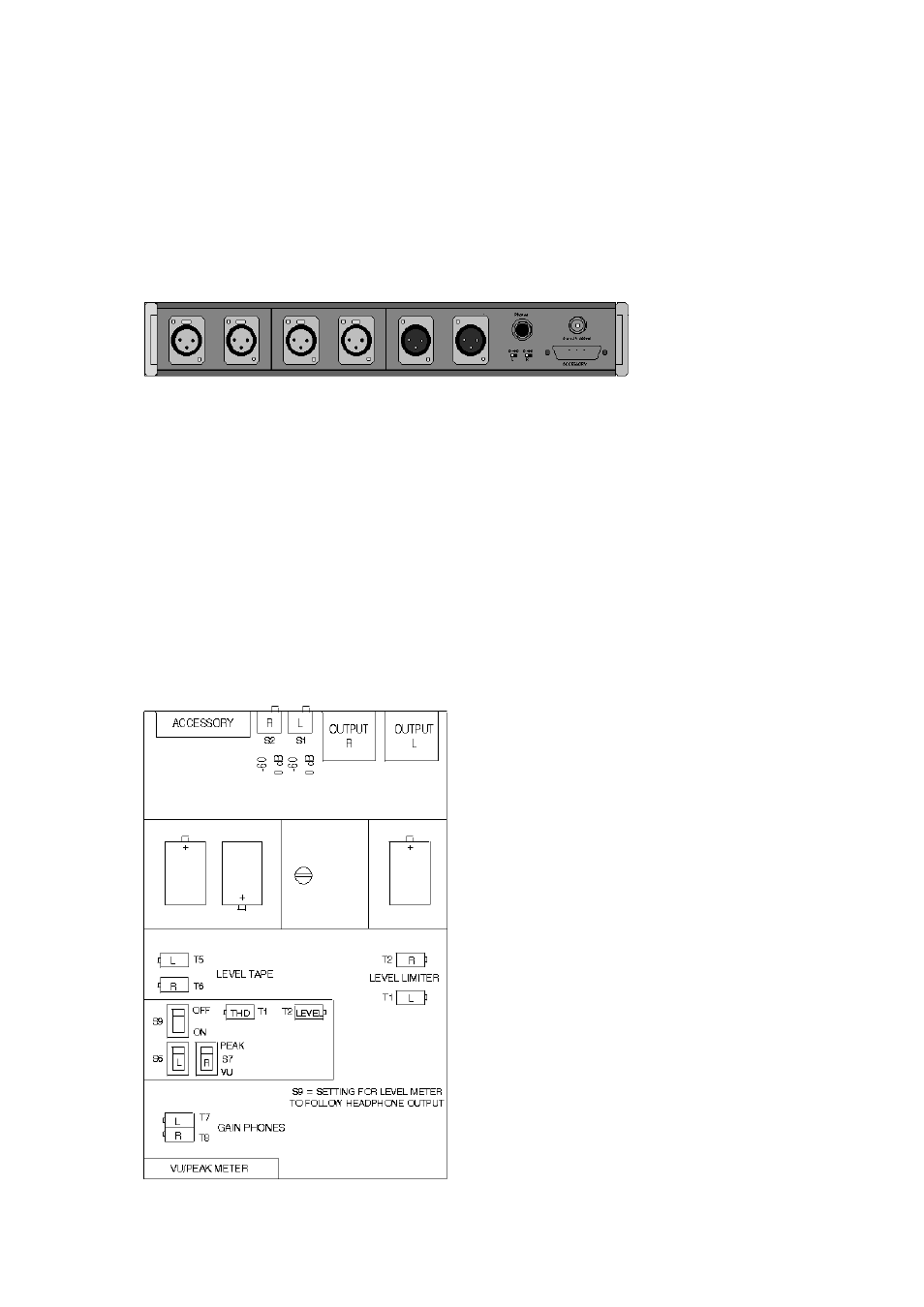
Rear pannel
MAIN OUTPUTS
The XLR connectors provide the signal at a maximum level of +18dBu (600W ).) Unbalanced
connection is possible by bridging one of the pins to the ground (observe the correct phase).
0/-60dB
To adapt the outputs to the microphone inputs of the recorder the level can be lowered by 60 dB.
PHONE
Hedphone output (6,3mm/ .25 inch jack) max.+15dBu (200W )
EXT. PSU
Coax-socket (5,5mm with center pin 2,1mm) 6-12V DC max 500A.
ACCESSORY
The 9-pin Sub-D-connector provides an
additional symmetrical output and the input for
the tape return (+6dB).
1 Output R lo ( XLR Pin 3)
2 Ground
3 Output L lo (XLR Pin 3)
4 Tape return L
5 Tape return R
6 Output R hi (XLR Pin 2)
7 Output L hi (XLR Pin 2)
8 Ground
9 Ground Tape return
4. Mechanics
The modules are hold together by 4 bars screwed to the left and right hand side pannels. A fifth bar is used to hold the lids covering the battery housing and the the less often used
settings of the input modules.
This construction makes it possible to change the size of your mixer by adding or taking off one input module or, if this is desired turn it into a left hand mixer.
The electronic connection between modules is made by 10 pin connector bridges which require special attention when dismantling the unit.
5.Internal Settings