SP Controls PXE-EMIT-REL2 PixiePlus User Manual
Pxe-emit-rel2 pixieplus relay controller, Simple. intuitive. control
PXE-EMIT-REL2 PixiePlus Relay Controller
The PXE-EMIT-REL2 relay dongle is for use with the PixiePlus
TM
Device Control Module (PXE-
DCM+). The PXE-EMIT-REL2 contains two low-voltage control relays which may be configured to
open and close momentarily or continually. Relay events are activated by button presses on the
PixiePlus control interface. The Bus Status LED on the PXE-EMIT-REL2 glows green when relay 1
is closed, red when relay 2 is closed, and amber when both relays are closed.
Requirements
The PXE-EMIT-REL2 is for use with the PixiePlus Device Control Module (PXE-DCM+) with
firmware v53 or later. The PXE-EMIT-REL2 is not compatible with the basic Pixie
TM
(PXE-DCM).
Configuration of the PixiePlus for use with the PXE-EMIT-REL2 requires the SP Controls Program-
ming Wand (PXE-PGM-TOOL, sold separately), with Configuration Utility v2.02 or later.
Configuration Overview
PixiePlus relay actions are specified by commands that are entered into the Code Data field of the Configuration Utility. To
program a button to initiate a relay action, click the green plus box to add a code. The BAUD and Com Port settings may
be set to any value; they will not affect relay actions.
Example 1:
&BUS(U,*,RELAYS,CLOSE-1-ONLY)
In this example code, pressing the button causes Relay 1 to close on a PXE-EMIT-REL2. The variables U and Relays will
never change, and the * is rarely modified. In practice, most relay commands will be one of the following:
&BUS(U,*,RELAYS,CLOSE-1-ONLY)
&BUS(U,*,RELAYS,CLOSE-BOTH)
&BUS(U,*,RELAYS,CLOSE-2-ONLY)
&BUS(U,*,RELAYS,CLOSE-NONE)
For momentary closure, you must add a command for the relay to close, then specify a delay of the desired closure pe-
riod, then a command for the relay to open.
Example 2: &BUS(U,*,RELAYS,CLOSE-1-ONLY),d500m,&BUS(U,*,RELAYS,CLOSE-NONE)
In this example Relay 1 will close for 500 milliseconds, then open.
Example 3: &BUS(U,*,RELAYS,CLOSE-BOTH),d2s,&BUS(U,*,RELAYS,CLOSE-NONE)
In this example both relays close for 2 seconds, then open.
For complete instructions on configuring the PixiePlus for relay actions see the Help File in the PixiePlus Configuration
Utility v2.02 or later, available on the Programming Wand.
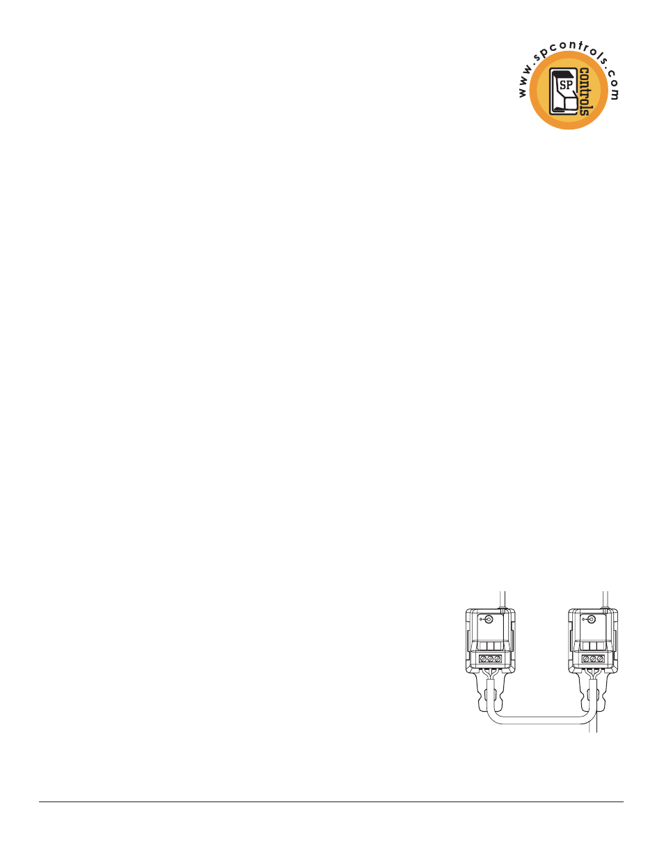
Connection
The PXE-EMIT-REL2 may be wired to the PixiePlus control module along with the
IR/RS-232 control output in either a “home run” or daisy-chain configuration (see
wiring diagram).
Relay 1: Blue
Relay 2: Green
Specifications
Relay rating: 400mA at 48V.
Power: 6VDC, 300mA
Caution: The PXE-EMIT-REL2 is for low voltage control only and under no circumstances should it be connected to
high voltage.
Simple.
Intuitive.
Control.
SP Controls Inc. 930 Linden Ave S San Francisco, CA 94080 phone: (877) 367-8444 fax: (415) 642-2605 email: [email protected]
+6V
BUS
GND
BUS
Activity
POWER
300 mA
6 VDC
BUS
Activity
POWER
300 mA
6 VDC
+6V
BUS
GND
relay 1 = blue
relay 2 = green