V. wiring – SP Controls PixiePro User Manual
Page 10
V. Wiring
A. Wiring Controller
Wiring PixiePro to Control a Single Device
Attention! Remove power from the IR emitter
before wiring to PixiePro. Do NOT attempt to
connect the wires to the PixiePro while it is pow-
ered. Doing so may damage the unit.
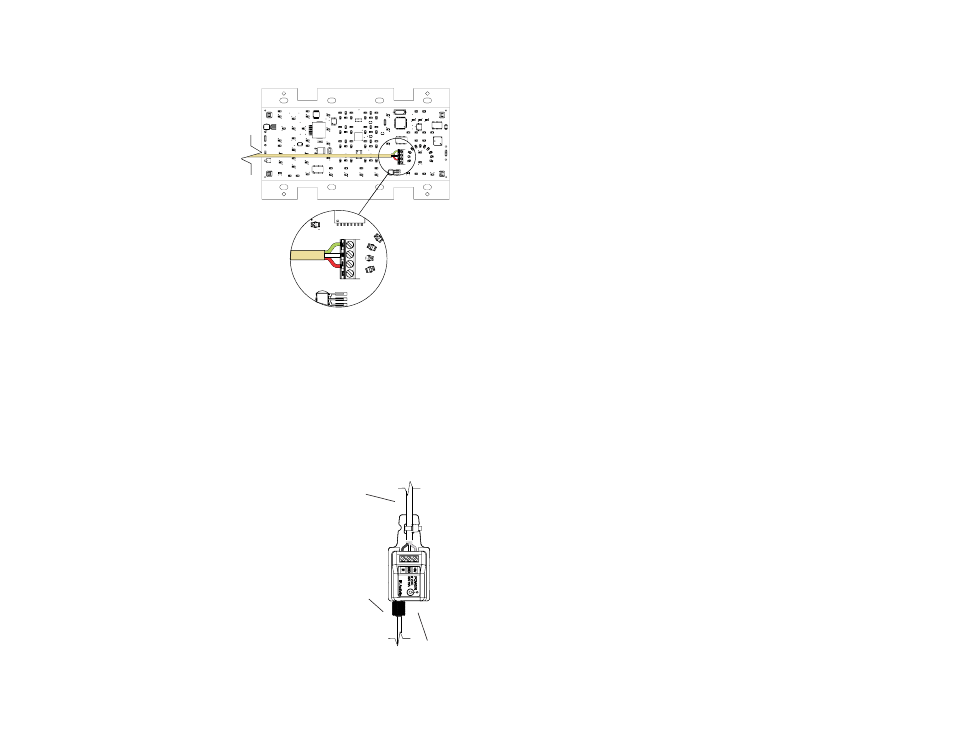
Connect the three-conductor cable to the captive-
screw connector on the back of the PixiePro. Be
sure that the wires agree with the connections on
the cable assembly block end (diagram below).
Note: The output position labeled RS232TX and
the female RJ45 port on the PixiePro are for
future use with other SP Controls hardware.
Wiring PixiePro to Control Multiple Devices
The PixiePro ships with just one IR emitter; each
additional device that the PixiePro controls will
require an additional IR emitter (not included, part
no. PXE-EMIT).
Note: The PixiePro may be used to drive a maximum of six IR emitters with a single power supply.
To drive more than six, additional power supplies must be ordered (part no. PXE-DCM-PS).
All three wires of the PixiePro output must be wired in parallel to each emitter that will control a
device. The cable assembly blocks may be wired in a star pattern out from the back of the PixiePro,
or daisy-chained from one assembly block to the next, use whichever method requires the least total
line length.
For a diagram of daisy-chained wiring between two IR emitters, see Figure 9 on page 8.
B. Wiring IR Emitter
Wiring IR Emitter to Control a Single Device
Attention: The optical fiber that extends from the PixiePro terminal
block cannot be extended. DO NOT CUT it without proper fiber optic
cutting tools.
Wire the cable assembly to the PixiePro using a three-conductor
cable (not included). SP Controls recommends using 18- or 20-
gauge cable. Standard audio cable will work (e.g., Belden™ 8451
or 9451).
1. Wire Cable Assembly. Connect the three-conductor cable to the
screw down posts in the cable assembly block. The three positions
on the cable assembly block are labeled +6V, GND, and IR. Match
the conductors to the corresponding positions on the captive screw
connector on the back of the PixiePro.
IR
+6
GND
RS232 TX
IR
+6
GND
RS232 TX
3-conductor
to PixiePro
Fiber Optic
Cable to IR
Receiver
Window
Connect
6 VDC
7
Figure 7: IR emitter
Figure 6: Wiring the controller