SP Controls SLB-MINI-KEYLOCK User Manual
I. overview, Ii. smartpanel configuration, Iii. installation
SmartPanel Accessory Installation Note
SLB-MINI-KEYLOCK
Revision A
1/20/09
SP Controls reserves the right to modify specifications without notice at any time.
I. Overview
The Mini Patch Module Keylock (SLB-MINI-KEYLOCK) may be installed in conjunction with the SP
Controls SmartPanel (SP2-CHAS, SP2-SMCHAS) in order to prevent unauthorized use of display
equipment. When the Keylock is set to the Locked position the SmartPanel cannot be turned on –
pressing the Power On button will cause a red LED on the Panel to illuminate, but it will not turn on, send
an on command to the projector, close any power on relays, et cetera.
When the Keylock is locked, the SmartPanel will work normally except for the power on command being
disabled. This will allow an installation to be locked and used normally until it is powered off.
Firmware requirements: To use the SLB-MINI-KEYLOCK the SmartPanel must run firmware version
1.0 or higher (began shipping March, 2003). A SmartPanel firmware upgrade can be ordered if necessary
(part no. SP2-FW-UPG-V1.x).
II. SmartPanel Configuration
The SmartPanel is configured to use the SLB-MINI-KEYLOCK during projector driver configuration with
the SP Controls Product Configuration Utility. On the Configure Wiring page, select the Keylock option in
the Accessories pulldown menu.
When you have selected the correct configuration, download the settings to the SmartPanel. For more
information on configuring the SmartPanel, see the SmartPanel Installation and Configuration Guide.
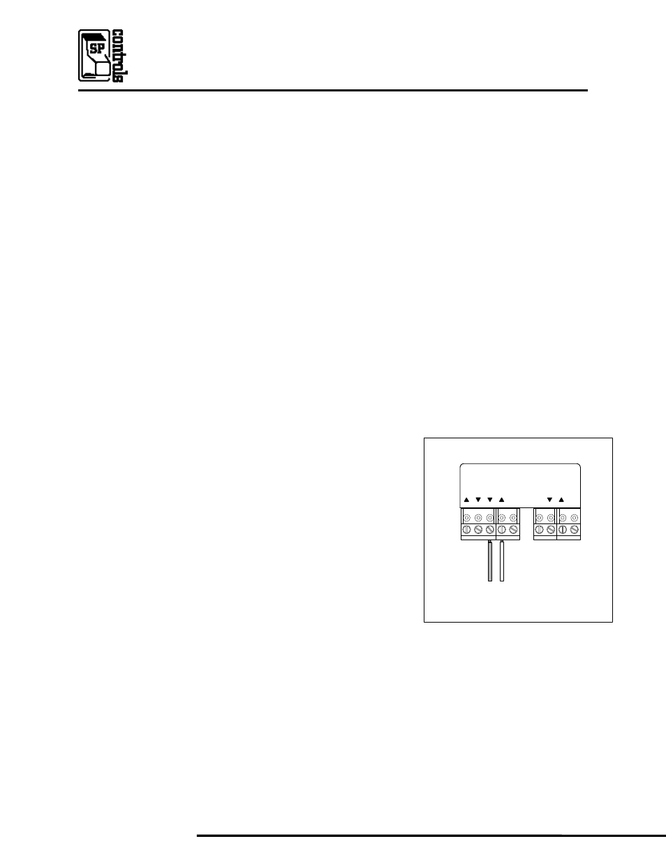
III. Installation
Connect the wires protruding from the back of the Keylock module to
the SmartPanel captive screw terminal positions labeled RTS and CTS.
The wires may be extended a few hundred feet if necessary.
The Keylock module may be installed in one of the four cutout slots in
the SmartBox SLB-SBOX MINIFACE or SP2-RACKSM-MOD if desired.
IV. Keylock and other SP Controls Products
The SmartPanel may be locked without a hardware interface through
the CatLinc Net network controller (. In installations including both a
CatLinc Net and a SmartPanel, an unlock command from either source
will override any lock command. For example, a CatLinc Net unlock
command will override a locked Keylock module.
The Keylock module may also be used with the Networked Room Controller (PX2-NRC-1142). When
wired to one of the NRC Sense ports, the Keylock can be configured to lock or unlock the NRC system,
or perform other functions.
V. Revision History
Revision A (January, 2009) – Initial release. BT
RS232
IR/SERIAL
RX
GN
D
CT
S
RT
S
TX
+12
V
GN
D
IR
/S
E
R
SE
N
S
E
Back of SmartPanel
Wire RTS and CTS to Keylock
(color sequence does not matter)