Spohn 782-F User Manual
Page 2
Note: We have installed either polyurethane or Delrin® bushings, both of these are
much more resistant to flex than the factory rubber bushings, so it may be necessary
to tap the a-arm into the k-member mounts using a soft hammer.
16. Install the fully compressed coil spring into the top spring mount in the k-member.
Then swing our lower a-arm up and guide the bottom of the coil spring over the short
spring centering tube that is welded to the bottom of our lower a-arm's spring pocket.
Make sure that the coil spring is properly clocked. The end of the coil spring should
butt tightly against the face of the spring ramp that is welded to the bottom of our
lower a-arm's spring pocket.
17. Position a jack under the a-arm in the area of the ball joint.
18. Remove the wire or rope you used to tie up and support the spindle, brakes, etc.
19. Jack up on the a-arm until the ball joint is fully seated in the spindle. Install the
supplied castle nut and fully tighten, then install the supplied cotter pin and bend it
over. Remove the jack.
20. Loosen the internal spring compressor and remove it through the bottom of the a-arm.
Make sure the coil spring remains clocked correctly against the face of the lower spring
ramp when the spring is fully uncompressed.
21. Repeat Steps 4-20 on the passenger's side of the vehicle.
22. On both sides of the vehicle loosely connect the top of the sway bar end links to the
front sway bar. The bottom of the end link is fully installed and tightened when we
assemble the a-arm. Remove the Nylock® nut from the top of the end links and then
sandwich the front sway bar between the two bushings (same as the factory end link).
Then install the 3/8” Nylock® nut and make it snug, but not fully tightened.
23. Safely lower the vehicle to the ground.
24. With the vehicle on the ground and the suspension loaded, tighten both of the
mounting bolts that go through the a-arm bushings at the frame mounts on both sides
of the vehicle.
25. With the vehicle on the ground and the suspension loaded, tighten the 3/8” Nylock®
nut on the top of both of the front end links. Tighten the nut until you see the
bushings starting to deform, then STOP.
26. Grease all four of the bushings (two per side) through the grease fittings. 4-5 pumps
from a grease gun in each bushing is plenty, do not grease more than that.
VERY IMPORTANT: The bushings come pre-lubed. DO NOT use any petroleum based
grease on polyurethane bushings! Polyurethane bushings must be lubricated with
synthetic silicone based waterproof grease. These are the bushing manufacturer’s
recommendations to prevent premature bushing wear, and will keep things "squeak-
free". You can order this grease from Spohn Performance using our Part# 902.
Do not over grease the bushings! You only need a couple pumps of grease.
Over greasing will cause the bushings to balloon from the hydraulic pressure
inside of the bushing sleeves and they will fail!
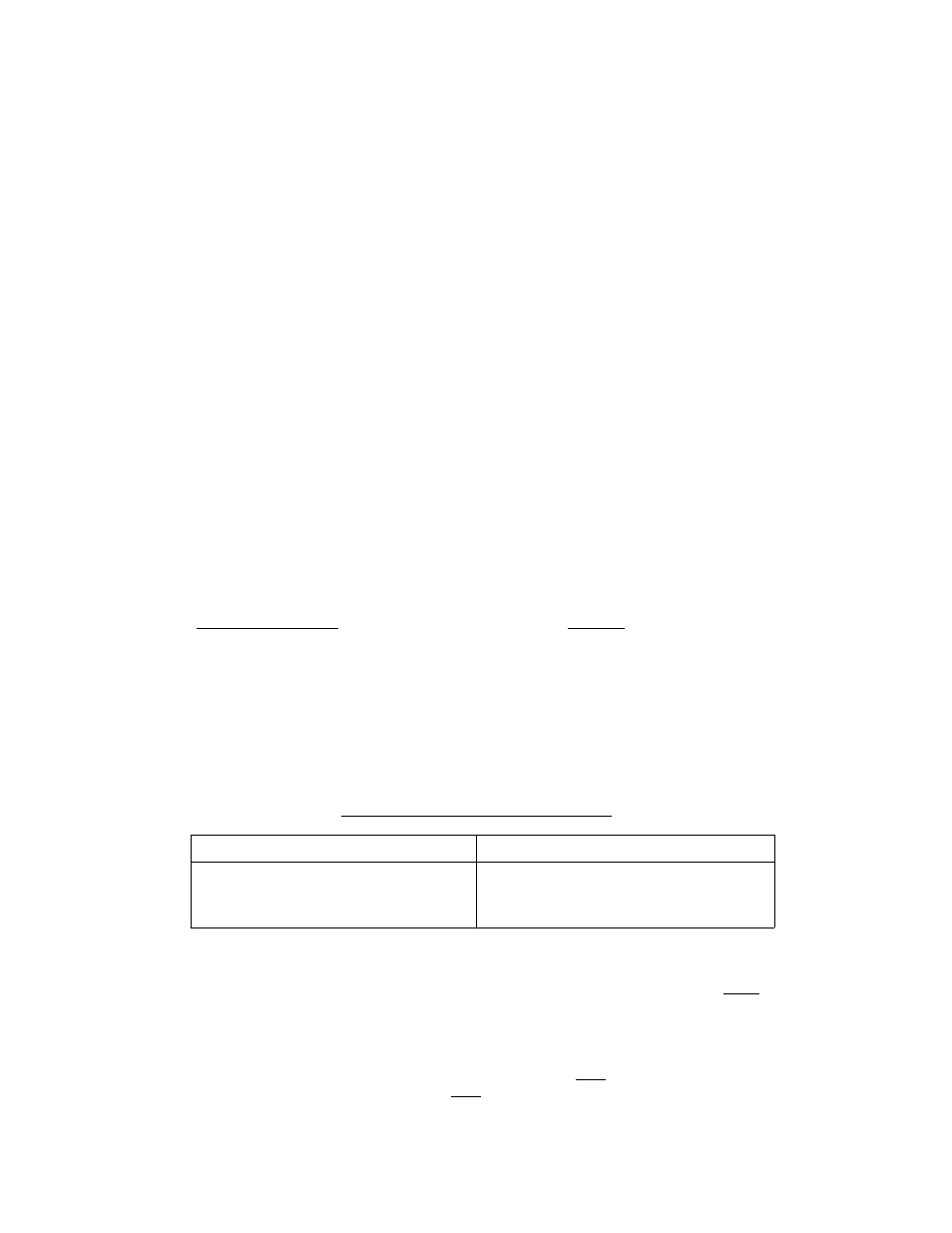
Recommended Alignment Settings
Left Side
Right Side
Caster: 4.5° Positive
Camber: 0.5° Negative
Toe-In: 3/32” Total (.05° per side)
Caster: 4.5° Positive
Camber: 0.5° Negative
Toe-In: 3/32” Total (.05° per side)
Fitment Note: If you install our Part# MR-8292F Pinto Manual Steering Rack you must use
our Part# 781-F-MR or 782-F-MR tubular a-arms. Those a-arms have longer than stock
steering stops that limit the turning radius to be compatible with the Pinto rack and pinion
steering.
Make sure your tubular a-arms match your steering type. Do NOT use Part# 781-F or 782-F a-
arms with a Pinto manual steering rack. Do NOT use Part# 781-F-MR or 782-F-MR with factory
type steering. See the chart on the next page for proper a-arm fitment applications.
2