Spohn BRG-000951 User Manual
Spohn For the car
Instructions for ’03 - ’08 Dodge 2500-3500 4WD & 1500 4WD Mega Cab
Part # 000951
CAUTION: NOT ALL VEHICLES CONFORM TO PUBLISHED SPECIFICATIONS! TEST FIT THIS
ASSEMBLY IN YOUR TRUCK BEFORE PAINTING OR ALTERING IN ANY WAY. ONLY ASSEMBLIES IN
NEW CONDITION WILL BE ACCEPTED FOR RETURN OR EXCHANGE.
REMOVAL:
1.
Engage the ignition switch / steering column lock with the steering wheel & wheels centered. (NOTE It may be
necessary to remove the bolt joining the two shaft assembly’s prior to locking for accessibility)
2.
Remove the bolt joining the two stock shaft assemblies just below the accordion boot and separate upper and lower
shaft assemblies. (Upper shaft collapses inside itself for removal.) Remove the pinch bolt on the stock lower shaft
assembly and remove from steering box. Remove the pinch bolt at the steering column just above the brake pedal
inside the truck cab and remove the upper shaft assembly with the firewall boot/seal. USE CARE WHEN
REMOVING FIREWALL BOOT AS IT IS NEEDED TO INSTALL NEW SHAFT
3.
Remove the firewall boot from original shaft assembly by cutting the metal clamps that hold the accordion boot to
factory shaft and remove. You should now be able to slide the firewall boot off the old shaft. Re-install firewall boot
in the truck.
INSTALLATION:
4.
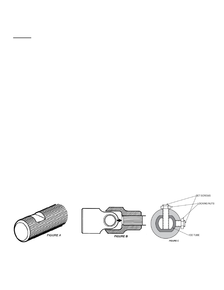
Remove universal joint from upper tubular half of the new Borgeson shaft assembly buy 1
st
loosening both set screws.
One set screw is very long and must be removed all of the way. (See Fig. C) Remove universal joint and slide the new
shaft thru firewall and re-install the universal joint being sure to tighten set screws and then lock nuts. (See Fig. C)
5.
With the Borgeson shaft assembly full collapsed. Install upper end of new shaft assembly over column shaft, be sure
not to insert shaft too far in to joints. (See Fig. B) Tighten set screws and then lock nuts.
6.
Slide the steering box universal joint over the splined steering box input shaft to the depth shown in Fig. B by
extending the telescoping shaft . A seat must be provided for the set screw as shown in Figure A. (NOTE The existing
factory flat will not be used) Tighten the set screw to mark the shaft and then remove the universal joint to file a new
flat spot on the splined shaft. Tighten the set screw into the seat and then tighten the lock nut.
7.
After approximately 100 miles, loosen lock nuts and retighten set screws and then lock nuts. We recommend Loctite
222 for ease of removal.
Borgeson Universal Co., Inc.
91 Technology Park Dr. Torrington, CT 06790
860-482-8283 www.borgeson.com
5/8/08