Grounding and shielding – Studio Technologies 220 2004 User Manual
Page 27
Issue 2, August 2004
Model 220 User Guide
Page 28
Studio Technologies, Inc.
utilized, the trim pots can be used to either
adjust the absolute level each line input
signal, or to adjust the relative level of the
signals when compared to other sources.
The following examples may provide
some clarification.
Let’s begin with an application that has
a stereo cue source connected to the
line inputs. The source selection DIP-type
switches are configured to create a stereo
headphone output with line input 1
assigned to the left channel and line input
2 assigned to the right channel. Begin
the trim pot adjustment process by mov-
ing the user level controls (located on the
front panel) to their detent (50% of rota-
tion) positions. Then, with the stereo cue
source providing signal at its normal level,
adjust the trim pots to provide a comfort-
able level to the connected headphones.
The user can now, in response to chang-
ing conditions, adjust the front-panel level
controls as desired. Returning the con-
trols to their detent positions will always
provide the “reference” level to the head-
phone output.
A second example has the IFB input and
line input 1 both providing cue sources.
Channel 1 of the IFB circuit supplies
program-with-interrupt audio that is routed
to the headphone output’s left channel.
Channel 2 of the IFB circuit supplies
program-only audio that is routed to the
right channel. Line input 1 is connected to
an audio source associated with a sports-
event “spotter” position. This source is
routed to the headphone output’s right
channel. The input trim pot associated
with line input 1 can now serve a critical
role—adjusting the relative level of the
“spotter” audio as compared to the level
of IFB channel 2. The trim pot allows the
desired “mix” to be created, providing the
user with an effective cue signal.
Technical Notes
Grounding and Shielding
As previously discussed in this user guide,
the pin 1 connections on the main and
talkback outputs’ 3-pin male XLR-type
connectors are “floating,” i.e., not con-
nected to anything within the Model 220’s
enclosure. Some audio experts might take
offense to this, grousing that this should
have been left to the user or installer to
be connected or disconnect as desired.
However repeated field testing found that
floating pin 1 on the outputs was the key
to maintaining quiet audio. From Fenway
Park, to the Orange Bowl, and then north-
west to Husker Stadium, lifting pin 1 did
the trick.
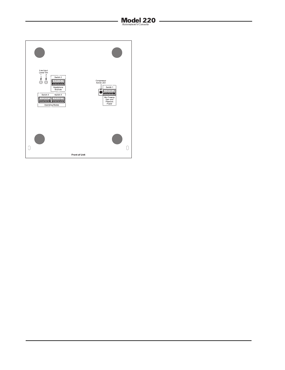
Figure 17. Bottom view showing line input
trim pots