Operation, Conclusion – Studio Technologies 230 2014 User Manual
Page 28
Issue 9, November 2014
Model 230 User Guide
Page 28
Studio Technologies, Inc.
selects which control is used for sidetone
level and which control is used to adjust the
level of the externally provided cue sources.
However, the headphone control mode that
selects between dual channel (“level/level”)
and stereo (“level/balance”) is no longer
active.
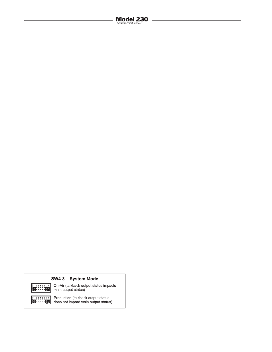
System Mode
Switch SW4-8 is used to configure the
overall operating mode of the Model 230.
Understanding how the two modes impact
overall system operation will ensure that
correct operation and maximum usabil-
ity will occur. When selected to the on-air
mode, the main output will mute whenever
a talkback function is active. The on-air
mode should be selected for all on-air
broadcast applications. It’s imperative that
the main output be muted whenever on-air
talent is using one of the talkback functions
to communicate with production personnel.
When the system mode is set for produc-
tion, the main output is never muted in
response to a talkback function being
active. It is controlled only by the main
output pushbutton. This mode allows the
main output to be used, for example, as an
additional talkback output. In this way, the
main output and talkback output functions
can be used independently with neither im-
pacting the other. This also allows all three
buttons to be used simultaneously. Note
that as is always the case the audio source
for the main output is the output
of the microphone preamplifier.
In summary, when selected for the correct
application, each of the system modes
can prove to be very useful. A thorough
study of how they impact the Model 230’s
operation can lead to many interesting
and powerful uses.
Conclusion
Once the switches have been set to the
desired configuration, it may be time to
reattach the security plate. The exception
is if the trim pots associated with the line
inputs and talkback-to-intercom sidetone
need to be adjusted. Details are provided
later in this user guide. The plate attaches
using the four rubber bumpers. They
should be hand-tightened only; no tools
are to be used.
Operation
At this point the desired input, output, and
power connections should have been
made. The button labels may have been
revised. After carefully reviewing the appli-
cation, the configuration switches should
have been set. Normal operation of the
Model 230 can now begin. The unit will
begin functioning as soon as a power
source is connected. As previously dis-
cussed, power for the Model 230 can be
provided by an IFB circuit, an intercom
line, or an external source of 24 volt DC.
It’s important to highlight the fact that
the Model 230 is an active device. Audio
signals will not be present on the outputs
unless correct power has been supplied.
Specifically, the microphone does not
passively “cut through” to the main output
XLR connector!
Upon Model 230 power up, the four status
LEDs will light in succession as a firmware
“boot up” indication. The unit will then
Figure 20. System mode settings