Studio Technologies 65 User Manual
Page 22
Issue 4, January 2004
Model 65 User Guide
Page 22
Studio Technologies, Inc.
for Surround
signal path to simulate the bandwidth
restrictions found with some digital audio
distribution formats. The low-pass filter
section is made up of four 2
nd
-order Sallen-
Key filter circuits that are cascaded, i.e.,
connected in series. Components were
selected at the factory so that the filter
section’s output has its –6dB point at nomi-
nally 120Hz. For some applications it may
be desirable to revise the frequency of the
low-pass filter. For example, in the future
it’s possible that the –6dB point may need
to be configured for 80Hz, matching the LFE
encoding parameters as proposed by the
creators of several formats.
As received from the factory two 8-pin SIP
resistor packages are used to implement
the 120Hz frequency. Two 8-pin sockets
located on the printed circuit board are used
to hold the resistors. To achieve the 120Hz
frequency requires two SIP different resis-
tance values. An 8-pin 6.8k SIP is “shared”
by the first two filters, while an 8.2k SIP is
used by the third and fourth. For simplicity,
eight ¼-watt, 1%-tolerance resistors of
identical value should be used to implement
a revised frequency.
The formula to determine the resistance
required for a specific filter frequency is:
R = 900,000 ÷ F, where R is resistance in
ohms and F is frequency in hertz. As an
example, to revise the low-pass filter for
80Hz eight 11.3k (11,300) ohm resistors
should be used.
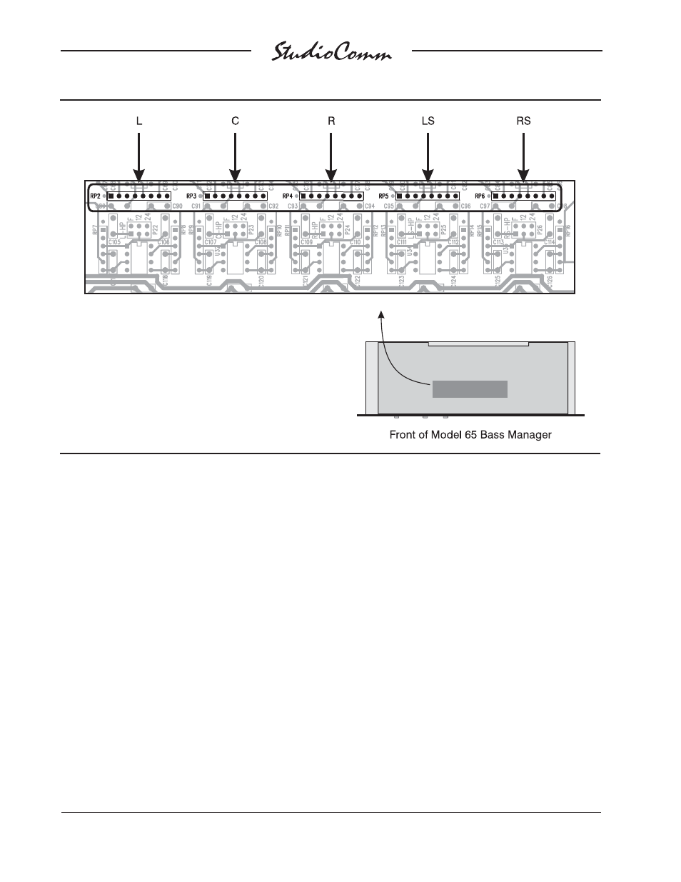
Figure 10. Main Input Low-Pass Filter Frequency Configuration