Cable modes – Studio Technologies 92 User Manual
Page 11
Model 92 User Guide
Issue 1, December 2006
Studio Technologies, Inc.
Page 11
Model 92 will not cause it to change or revert
to a “default” setting. The exception
is in the master-slave situation where a
Model 92 configured for master-male active
or master-female active can “force” its com-
panion unit into the slave mode.
Cable Modes
The Model 92 offers four cable modes. Refer
to Figure 4 for more details. The FK37 to
FK37 cable mode allows testing of DT12
assemblies that have a male FK37 connec-
tor on one end and a female FK37 connec-
tor on the other end. These are typically
referred to as “standard” DT12 cables. Refer
to Appendix B for DT12 wiring details. In the
FK37-M to XLR-F cable mode the Model 92
is ready to test DT12 cable assemblies that
have a male FK37 on one end and twelve
3-pin female connectors on the other. This
type of cable assembly is typically referred to
as a DT12 “fanout.” In the FK37-F to XLR-
M cable mode the Model 92 is configured
to test DT12 fanout assemblies that have a
female FK37 on one end and twelve 3-pin
male connectors on the other. The XLR to
XLR cable mode allows testing of standard
audio cables that have a 3-pin male XLR
connector on one end and a 3-pin female
XLR connector on the other end.
To select the desired cable mode is simple.
Press and hold the button to the left of the
up arrow; the Model 92 will slowly “cycle”
among the four choices. To select the
desired cable mode, release the up but-
ton when the appropriate indicator light
is active. The decimal point portion of the
displays is used to indicate the active cable
mode. The selected cable mode will remain
in effect until it is manually changed. Power-
ing cycling the Model 92 will not cause it to
change or revert to a “default” setting.
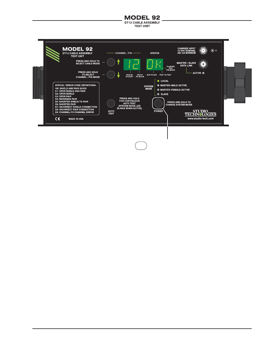
Press and hold power
button to cycle through
system modes.
Figure 3. Model 92 Configuration—System Modes