Super systems inc – Super Systems DP2000 User Manual
Page 7
SSi
Super Systems Inc.
Product Manual - Model DP2000 Portable Dew Point Analyzer
SSi Manual 4545 – DP2000
Super Systems, Inc.
Page # 7 of 17
Revision Level “F”
(800
) 666-4330
1.1 Remove the aluminum faceplate of the DP2000 by removing the single
allen-head cap screw located at the bottom front of the faceplate. After the
screw has been removed, carefully lift the front of the faceplate and slide it
towards you about an inch. After the faceplate has been removed, it can
temporarily be rested in the lid of the open case, to allow access to the
components inside. This plate will still be connected to the interior circuit
boards, so care should be taken to maintain all existing connections.
2.0 Locate the key components within the unit
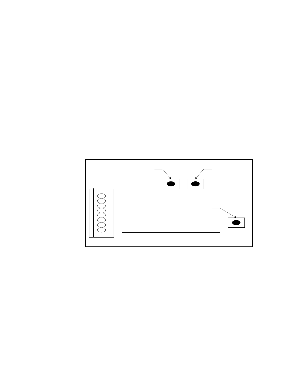
2.1 The microprocessor board is located in the front left side of the unit.
This board contains three very small buttons that are used for calibration.
Two are next to one another, and they are marked “75.3%” and “11.3%”,
while the other has no label. The unmarked button is the “Calibrate” button.
The approximate locations of each button are shown on this diagram:
2.2 The sensor-sampling chamber is located in the back left of the unit. It is
the gray rectangular box with brass barb fittings on either side with a black
plastic gland protruding from the center.
2.3 The sensor probe is positioned in the sensor-sampling chamber. It is held
in place by the nut on the black plastic gland.
3.0 Remove the sensor probe from the sensor sampling chamber.
3.1 Loosen the black plastic gland nut and slowly slide the sensor probe out
through the airtight seal. Care must be taken when removing this sensor probe,
SPAN
BUTTON
(75.3)
ZERO
BUTTON
(11.3)
CAL
BUTTON
Dew Point Microprocessor Board